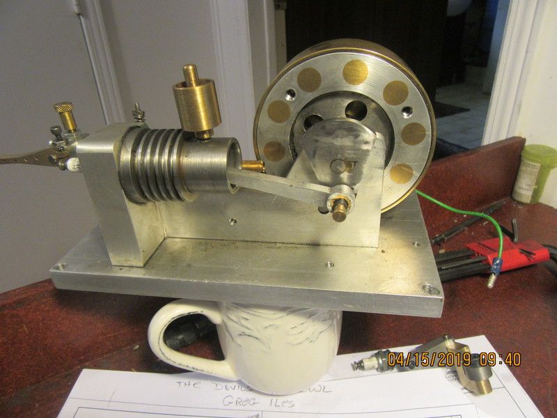
Werowance builds a webster

Home Model Engine Machinist Forum

Help Support Home Model Engine Machinist Forum:

This site may earn a commission from merchant affiliate links, including eBay, Amazon, and others.
Werowance.--P.D. is the pitch diameter, not the root diameter of the gear teeth. O.D. is the outside diameter, but you don't have anything on that chart that tells you what the root diameter is. When you mesh two gears, the center to center distance is 1/2 of the pitch diameter of one gear plus 1/2 the pitch diameter of the other gear. If you are making your own gears, I don't think you have all the correct information for doing it. The center to center distance in the downloaded plans is correct for the center to center of the correct gears as purchased from Berg. What you should do now, if you have kind of lost your place, is to take the two gears you have, mesh them with one and other, measure (as best you can) the center to center, then use that measurement to drill and ream correct size holes for stub shafts in a scrap piece of material and put the gears on the stub shafts and see if you can easily turn them by hand to see how they mesh. Once you have determined what that center to center distance is, you can use that on your engine. To plug a hole in aluminum, I generally turn a plug about .0005" larger than the hole to be plugged, cover it with Loctite, and press it into place. A vice can work to do that. Let it set up 24 hours, then file it flush on both sides and put the new hole in the correct place. The old timers would put a cigarette paper (which is 0.001" thick) between the two gears when they meshed them to give a little "running clearance". I don't do that myself.
 
well, all I have cut is the 24 tooth gear and I knew once I cut the blank I had already cut it to small so it was just a test. but the blank for the 48 tooth is right on for od. is there anyway to get the proper depth short of purchasing the gears? which I just may have to do
 
Tooth size is determined by #1--diametral pitch which is the number of teeth per 1" of pitch circle diameter. and by #1--Circular pitch CP which is the distance between adjacent teeth measured along the arc at the pitch circle diameter.
A stands for addendum which is the height of tooth beyond the pitch circle diameter.
CTT stands for circular tooth thickness which is the thickness of the tooth at the pitch circle diameter.
D stands for dedendum which is depth of tooth below the pitch circle diameter.
Pitch diameter is determined by number of teeth in a gear divided by the DP number
so for instance, a 18 tooth gear divided by the DP (24 in my case) will equal 0.75" P.D.
Outer diameter of a gear blank is determined by adding number of teeth plus 2 and dividing by the DP which in my case is 24---so 18+2 divided by 24=.833"outside diameter.
Depth of cut on a gear blank will be a constant of 2.157 divided by the DP---in my case with 24 DP gear cutters it will be 2.157 divided by 24 which equals .0899"--this depth of cut will remain the same for all 24 DP gear cutters.
The small 18 tooth Webster gear requires a blank 0.833" diameter. the depth of cut will be .0899"
It will require a #6 gear cutter.
 
werowance, if it's any help to you (or others), here is a link to one of my web pages,

https://www.vk7krj.com/Petrol electric1.htm

at the bottom of the page is a link to a downloadable spreadsheet I wrote that will calculate the various diameters needed for gear blanks. I mostly did it for the metric system, but it will also do imperial. I wrote it in Libre office, but there is an excel version there as well.

Ken, vk7krj
 
I think my repair came out pretty good for my first time. When Brian recommended "press fit" I cringed because sneaking up on that final .001 usually ends up either to big or to small every time for me. so I thought about it and figured I would try a taper plug. and on that I thought about the easiest way to do a taper plug and though why not use deflection to my advantage for a change. I cut down some old cattle trailer tarp bar from I got from a buddy that was scrapping an old trailer. the bar is the ones on top of a trailer that the tarp is streatched across. any way i turned a piece about 2 or 2.5 inches long and as i was getting to the .250 the deflection was happening and i was getting a taper. on small end i was about .254 and on big end i was about .2565 or .257 . the plug started in and then i pressed it on in and with about as much preasure as i felt was safe not to cause damage to the part i stopped pressing. i also used red high strength locktite. after that was all dry and setup i went to the disk sander and for a few seconds on it then a dunk in water so as not to over heat it and ruin the locktite. then the final little bit was done on my improvised surface plate with some 800 grit sand paper. with the camera zoom you can see the repair however its very hard to even see with the regular eye. thanks for the suggestion on how to do this Brian.

first pic is with it cut off and ready to start cleaning up.
upload_2019-4-2_8-56-49.png


upload_2019-4-2_8-57-29.png

upload_2019-4-2_8-57-57.png
 
well what a week last week....it was a busy one. this is all I got done since the repair. 2 gear blanks of the correct size and almost finished the piston. I do plan on trying rings first fully expecting to have to fall back to an o-ring piston. I'm also have a new grandson last week to. and spring has sprung here in Virginia - lots of yard work, mulch clearing old growth etc. then lastly my back went out. so guess what I'm saying is I really didn't get much in the way of the Webster build done but it was still a great week - so much new life happening.
upload_2019-4-8_9-7-15.png


upload_2019-4-8_9-8-1.png


upload_2019-4-8_9-10-33.png
 
we have gears this weekend! I think I did all right on them. next I think I need to start on the crank and rod. still considering doing a ball bearing on it. and on that note I have a question, does anyone know how much clearance there is on the rod and the base of the engine where it connects to the crank shaft? if I make the rod larger here to accommodate a ball bearing I am wondering if I will have enough clearance to make a full rotation without hitting the base or other things.

upload_2019-4-15_10-0-37.png


upload_2019-4-15_10-1-7.png


upload_2019-4-15_10-1-54.png
 
ok, ball bearings on order and working out the design for the crank, in particular the lack of a counter balance. I had considered doing a bolt on counter balance like the one I posted in Brian Rupnows thread that I had seen however if I just want to do a 1 piece setup would I start with a piece of 1.75 steel? (excuse the poor hand drawing)

upload_2019-4-15_15-45-16.png

upload_2019-4-15_15-50-6.png
 

Attachments

  • upload_2019-4-15_15-48-20.png
    upload_2019-4-15_15-48-20.png
    3.6 KB · Views: 159
I strongly recommend that you don't even try to make this a one piece crankshaft. This type of crankshaft lends itself very well to being "built up" from three pieces of stock. The easiest way to make this is to buy an undersize reamer to do the holes in the plate. I would recommend a 0.001" undersize reamer. Design your plate or flatbar section to have the shape of a counterweight. A little secret here--If you make the shafts from cold rolled steel, cold rolled comes in at 0.0005" undersize, which will give you an interference fit of 0.0005", which works quite well. If however, you buy drill rod, it comes in "on size" and will not fit thru a bearing of the same size, and gives a full .001" interference fit, which is almost too much. If you want, I can post a design for the counterweight section for you.---Brian
 
i was going to do it in 3 pieces, it was just the (I think its called "web") part with the 2 holes in it that I wanted to deviate from the drawings from. in order to get the weight part built in the web in one piece (the plans just call for a rectangle piece) wouldn't I need at least a 1.75 piece of round stock to slice that out of? now on the crs at .0005 under - that is something I didn't know and that is a very good tip. thank you for that one.
 
You would make the web from steel plate, not round shafting. It can be cut to shape with a bandsaw or hacksaw and drilled/reamed on your mill. I don't recall what thickness the web is just off the top of my head, but choose a standard plate thickness. I would suggest making it from cold rolled steel flatbar, then you won't have mill scale to contend with. I just looked at the Webster drawings and see that they call up the web as being 0.219" thick with a .031" boss on one side of it. I would just use 1/4" plate with no boss and cut a washer out of .031" shim stock to provide the spacer which the boss currently does.
 
ok, ball bearings on order and working out the design for the crank, in particular the lack of a counter balance. I had considered doing a bolt on counter balance like the one I posted in Brian Rupnows thread that I had seen however if I just want to do a 1 piece setup would I start with a piece of 1.75 steel? (excuse the poor hand drawing)

Nice job on your gears.

As far as the crankshaft goes, I made it from three parts - and designed the counter balance (web) precisely per the dimensions shown in Brian's message #47 of his Webster build log.

I started with 0.25" thick, 2" X 2" piece of piece of 1018 flat bar and first located and drilled the two holes for the pin and the shaft. Then I band-sawed it to a 2" disc.

Next, I mounted the part on a mandrel and turned it to 1.82"D, then faced it to produce the 0.5"D X 0.031" boss. Then I removed it from the mandrel and band-sawed/belt-sanded it to shape.

I assembled the three parts using soft silver solder. In order to get good capillary action, I sized the two holes for loose slip fits. So far, the solder has held.
 
Last edited:
Thanks for the info on making the web. curious why not use bar stock and part it off? yes its easy enough to use plate but now I'm curious about is there a structural reason for it?

and I got the ignition cam made last night.
upload_2019-4-17_9-9-26.png


upload_2019-4-17_9-9-53.png
 
Werowance--Making the web from plate or flatbar simply saves hour and hours of machining.--A note of caution here--The shafts which you will be pressing into the web plate.--Make them about 1/2" longer than they need to be, and slightly taper that last 1/2" in the lathe with sandpaper--not a machining operation. This taper will ensure that the shafts fit squarely into the plate and not at a slight angle. Press until the tapered portion of shaft sticks out beyond the far side of the web, then cut the tapered part off with a bandsaw or hacksaw.
 
Back
Top