


The picture below is the first engine I ever build, right after I got a lathe. It wasn't built for anything in particular, more practice than anything.
When I built this engine I tried to use materials that would wear well and not gall. I was pretty successful except for the valve\port face. I used bronze for the face and 360 brass for the valve and they do not get along, it does not seem to matter how much oil I use, the portface seems to gall.
The point of this whole post is that I used to have a chart with different metals listed and how well the metals would wear in pairs. I think each pair was rated poor, good, and excellent. I am hoping someone has a copy or something similar as I have lost mine. I would appreciate any help with this.
Thanx
MikeR C
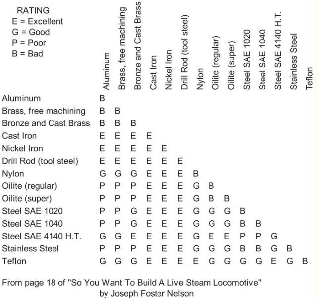
") ) I am assuming the table is available on your website, I will go look for it. I expect it may fine tune the chart above.
) I am assuming the table is available on your website, I will go look for it. I expect it may fine tune the chart above.