Water Pressure Engine..... Update

Home Model Engine Machinist Forum

Help Support Home Model Engine Machinist Forum:

This site may earn a commission from merchant affiliate links, including eBay, Amazon, and others.

Cedge

Well-Known Member
Joined
Jul 12, 2007
Messages
1,730
Reaction score
29
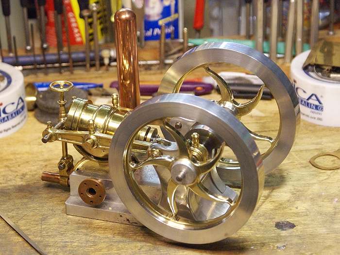
After letting the little Water pressure Engine sit on the bench half naked for too long, I finally got off my duff and went back to work to salvage its dignity. The huge heavy flywheel shown in the E.O.M. photo was only used for visual effect. The original plan was to have two flywheels, preferably with curved spokes.

I can't take credit for the idea nor the techniques used in making the flywheels shown below. The dearly departed Philip Duclos was the great mind behind all of that. I was just lucky enough to secure a copy of one of his magazine articles of the past from a very generous member of this board.

water-engine-flywheel.jpg


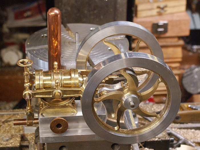
The photos show the flywheels fresh from the indexing table on my mill and have had little or no clean up done as of yet. There will be a good bit of hand work with a file, to come, but I thought I'd share the first test fit with you guys.

For those with sharp eyes and a bit of knowledge of the article, there is an obvious change from the plans that give the spokes an "S" configuration. Let's just call it one of those happy accidents that come via karmic serendipity. I'll be posting a build thread on the project, soon, which will explain just how an "AWWW $**T!!" moment was used to full advantage.

Steve
 
Nice job on those flywheels. :bow: :bow:

Could that "Awh S*^#& have been "the index went the wrong way" ? Looks like a bit of an "S" near the out side edge.

BTW I have Duclos's book. Nice book to have.

Bernd
 
Bernd
Very close guess....LOL. The indexer is a manually controlled fixture which uses a small hand held "Tommy bar" to control things. I got so engrossed with the process of cutting the outer radius that I broke my rhythm and wound up dropping the quill for a cut at the wrong end of the slot cut. Yup... it exited the slot doing the dreaded climbing cut. Theres a sudden lurch and the end mill was instantly sitting half way into the end curve of the preceding spoke.

Once upon a time that would have triggered the throwing gene, along with the mass obscenity hormones. I admit to tapping into the latter for a brief moment, but I just stopped and looked things over for a while. I then broke out a file and began to play with the problem. About 5 minutes of filing rendered the surprise of the "S". I continued to play a bit to see what could be done to salvage things and added some rounding to one of the spokes (back side in photo) and an elegant shape began to appear.

I only managed to avoid the scrap box by pure luck and a bit of contemplation. The second wheel got the "Awww $**t" cut intentionally and Steve once again attained inner peace...LOL

The project was my first, but not my last, attempt. I learned quite a bit and discovered some things about varying spoke contour from another mistaken assumption. Philip Duclos just didn't miss any tricks at all when he wrote up this project.

Steve
 
Steve,

Your PM'd description didn't do them justice.

They are

A-W-E-S-O-M-E

Sometimes little mistakes turn out to be massive discoveries, looks like your has worked very well indeed, and got around your little problem as well.

Looking forwards to the making post.

John
 
Very ........ very ............. Nice, ............ dam fine "recovery" job too :bow:

8)

CC
 
Steve, very nice! Great job with the spokes, and brilliant recovery! Some of my finest work comes after an "Oh Sh**" moment! :big:
 
Steve those turned out great. Did the original article you showed me have the spokes tappered. I was thinking they were the same thickness from center out. But you know how my memory is. Anyways I like the tapered spokes a lot better. I see they are not polished or deburred yet, so I assume this was one of those moments you just had to put them on the engine to see how they look. ;D
Make sure to post the finished pictures 'cause I have a feeling we haven't see in all yet :p
Tim
Better yet bring it over. :)
 
Thanks guys. It's been a fun project so far, with more than a couple of surprises along the way. The results blew me away too. Duclos was one smart cookie.

Zeusdude
The deburring began this afternoon, right after I posted this thread. Luckily I don't mind working with files. The spokes will be rounded a bit and then polished to high bling. The tapers are indeed different from the drawings. That is the result of a small misadventure that again... turned out well. Proving once again that I'd rather be lucky than good.

I have one side of the first flywheel filed and polished and I began working on the reverse side of the spokes and rim, but it's gotten late and me old body is ready for a break.

Are you sure it's safe for me to bring it over?.....LOL

Steve
 
Steve... :bow: :bow: :bow: As John said (I'll not put in all the funkey stuff!) AWESOME!

I really cannot wait to see the fully finished engine. Both in stills and a video.... I want to see it do what it does ;D


Ask John if he can lend you some Bling fairies to help you with all that polishing ;) :big:


I like some of those little 'errors' too.... Made my 2 efforts look a little different ... I like to call it artistic re-styling ;)


Just one simple question. Was the brass pressed in or the outer ring heated and fitted over the inner disc?


Ralph.
 
Lots of hand filing, a couple of Dremel tips and some metal polish plus a few hours of getting sore fingers, but things progress. Here are the two flywheels after getting a bit of love and attention. Still have to make the collar wedges for mounting them and a pair of gaskets are needed in the cylinder ends.

Steve

water-engine-flywheel3.jpg


Ooooooohh we! Man that was so bright. I got an instant migrane. Like looking into the sun. :big: :big: :big:
Those have to be some of the most beautiful flywheels I've ever seen.
 
Excellent Steve. :bow: :bow: :bow: :bow:

I needed a pair of sunglasses to look the engine over. 8) :big:

Very nice job on the polishing, well worth a couple of sore fingers. :)

Regards,
Bernd
 
Thanks Tim and Bernd.... I do like mine shiny. Tim... I'll bring my welding shield and dim the lights when I bring it over for a visit.

Ralph...
I actually used both methods. The outer rim inner diameter is .001 smaller than the brass. I was able to freeze the brass in my handy dandy shop beverage refrigerator while I was heating the outer aluminum rim with my propane torch. The cold brass easily dropped into the heated rim and began cooling it down, essentially making the two pieces one.

The inner hub is also aluminum and was machined for a fair interference fit and then pressed in place to avoid reheating the previous pieces. A bit of red Loctite was used to lubricate the joint as it was pressed in and to lock it in place for good. The resulting laminated discs were then faced to uniform thickness, on the lathe as single pieces.

The brass was cut way to a thickness of .250 with a round noised cutter, leaving the aluminum parts at .5625 (9/16 inch) thickness. The round nose left a nice rounding at the hub and the rim that blends right into the aluminum with an almost invisible joint.

The borrowed Bogster Bling Fairy almost met its end tonight when I mistook it for one of our more aggressive local mosquitos....LOL

Steve
 
Steve it is obvious that no one ever told you it is impossible to do
that kind of ornate metal work unless you have CNC capable machines.

Beautiful work!

Rick
 
All I can say is, "WOW!!!" That is a work of art! :bow:
 
Just ........... S T U N N I N G ....... 8)

May all your errors work out so well :bow:

CC
 
Wow... Steve... just wow.

That last picture just became a desktop background :bow:


Eric
 
Thanks Paolo... I think its a keeper....LOL


Steve
 
Back
Top