


C
chiliviking
Guest
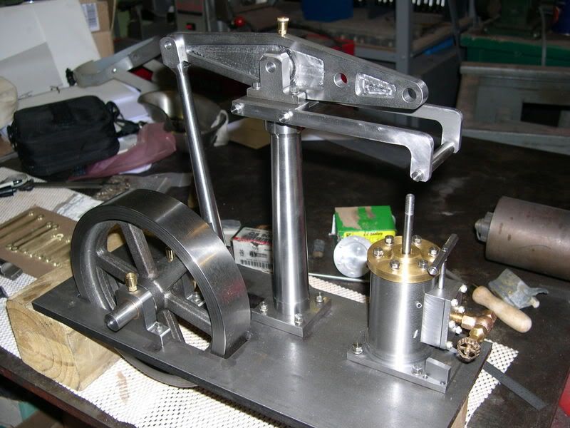
I've got some more work completed on my walking beam engine and while I have many more parts to go I can see the light at the end of the tunnel. Today I spent most of the day making a jig for rounding off the ends of the motion links.
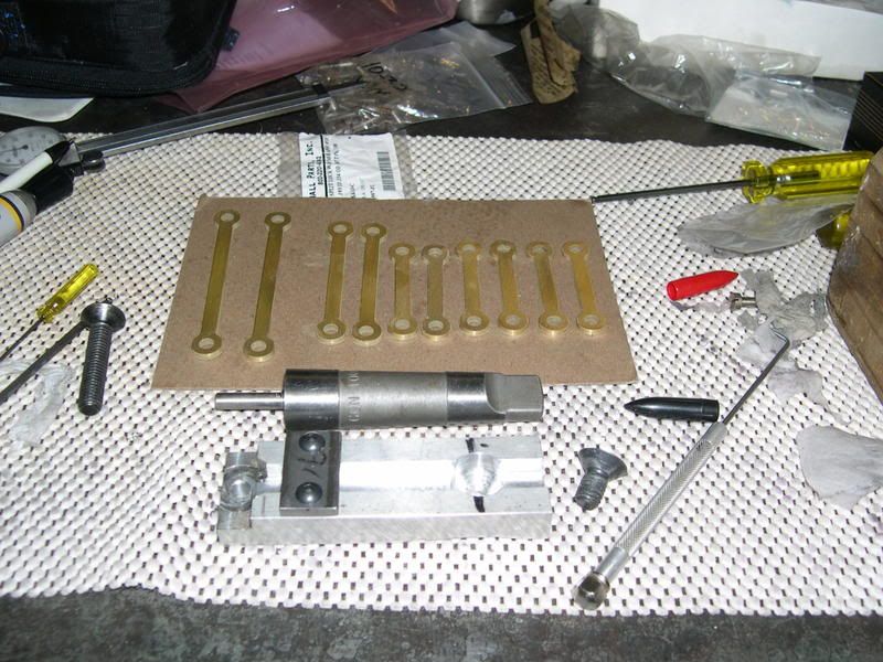
First I turned a .250 stub on the end of a morse taper piece that I had that fits in the center of my rotary table. Next I made a piece of aluminum with a hole to fit over the pin on one end and a countersunk hole on the other end to bolt the jig into a T-nut on the rotary table. Then I milled a slot down the center that was a nice slip fit for the pin blanks and deep enough to do two at a time with .025 sticking above the top sutface to clamp down on. I made a strap to hold the pieces down in the slot and drilled and tapped them 10-24.
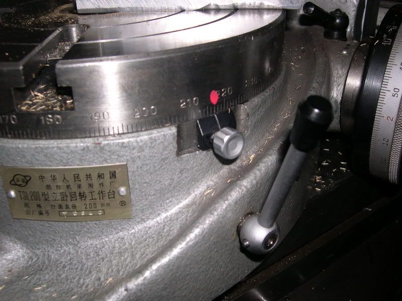
I figured the amount of rotation necessary on the table and marked the location with red fingernail polish. It only took about an hour to make the ten peices after the jig was completed.
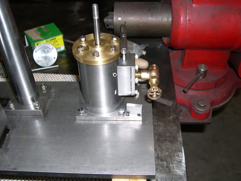
I have begun replacing the socket head cap screws with small hex head bolts which really inproves the overall look.
I got a 90 degree gate valve for the air inlet.
First I turned a .250 stub on the end of a morse taper piece that I had that fits in the center of my rotary table. Next I made a piece of aluminum with a hole to fit over the pin on one end and a countersunk hole on the other end to bolt the jig into a T-nut on the rotary table. Then I milled a slot down the center that was a nice slip fit for the pin blanks and deep enough to do two at a time with .025 sticking above the top sutface to clamp down on. I made a strap to hold the pieces down in the slot and drilled and tapped them 10-24.
I figured the amount of rotation necessary on the table and marked the location with red fingernail polish. It only took about an hour to make the ten peices after the jig was completed.
I have begun replacing the socket head cap screws with small hex head bolts which really inproves the overall look.
I got a 90 degree gate valve for the air inlet.
