Vedersteins Five Cylinder Wobbler Build

Home Model Engine Machinist Forum

Help Support Home Model Engine Machinist Forum:

This site may earn a commission from merchant affiliate links, including eBay, Amazon, and others.

vederstein

Must do dumb things....
Joined
Feb 26, 2011
Messages
917
Reaction score
744
I wasn't really sure if I wanted to document the build of my version of the "hula" engine. But my wife convinced me that it would be good to do so. Perhaps she thinks this idea has never been done before. I don't know. But she's probably right. If I don't document the build, others cannot learn from when I eventually screw up.

attachment.php


The plans are of my own and can be found here:

http://www.homemodelenginemachinist.com/showthread.php?t=26783

I had already made a few parts prior to taking pictures, so I cannot talk about those. They are bars with holes drilled in them anyways, so those are pretty easy.

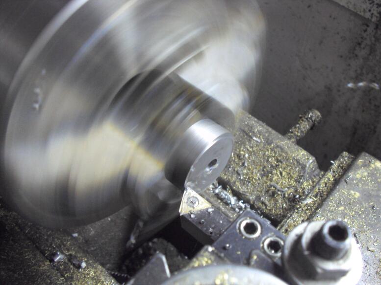
Otherwise I started with the main hub. This is probably the most complex part to make.

Because I used barstock of the correct OD to start with, I chucked the blank into the four jaw lathe chuck and centered the part. Three jaws are never perfectly centered I can be more accurate with the four jaw.

attachment.php


Then I faced off the blank.

attachment.php


From there I drilled and bored out the part.

attachment.php


attachment.php


DSC01622.jpg


DSC01624.jpg


DSC01625.jpg


DSC01627.jpg
 
Last edited:
After turning down to the correct width, I chucked the part into the mill on my rotary table where I would continue with the most difficult portion of this part - the pockets.

I didn't want to make one massive frame where one screw up can ruin hours if not days or work, so I designed the frame as a bolted assembly. As an industrial machine designer, I use the same philosophy in my designs for work. I prefer multiple simple parts over one excessively complex part.

I did find in machining the pockets it was best to cut the pocket about 0.005" undersized then make one, final climb cut to size. The finish was much better than my first pocket where I used a different technique.

attachment.php


attachment.php


attachment.php


attachment.php


attachment.php


I guess you can say at this point I made the world's most expensive Fidget Spinner.

attachment.php


DSC01629.jpg


DSC01630.jpg


DSC01631.jpg


DSC01632.jpg


DSC01633.jpg


DSC01634.jpg


DSC01635.jpg
 
Last edited:
None of the pictures work on my end. Would really to see them.
 
Barnsbikes:

I tried to work around the system to get my text interspersed with the photos. I guess my technique doesn't work. It looks fine on my screen. But you're right. I opened up this thread in another browser and nothing.

I'll edit my posts and fix it.
 
Looks good my end.

I'll look forward to following the build. Including learning from any cock ups you might make ;)

Jon
 
Another Sunday, another few hours to work on the engine...

Today I created the crankshaft, starting with the crank plate.

So it started as a piece of 1-1/2" dia. leaded steel. I turned it down to 1.44 per the print then drilled/reamed out the center.

The crank plate is only 3/8" wide and I didn't want to make a slug 3-4 times longer than the part where I generate a lot of swarf & scrap. So I use the full 12" long bar and supported it with a live center.

Then I cut it off with a bandsaw, flipped the part, and turned the part to the correct width.

DSC01636.jpg


DSC01637.jpg


DSC01638.jpg


DSC01639.jpg
 
Next was taking the plate to the mill. I used the rotary table to hold the part.

I drilled the hole for the shoulder bolt mounting threads. Then I did something I've never done before.

I drilled 3/8" holes for the cutout corner. Using those two holes with pins temporarily installed I clamped the part into the vise with a parallel underneath to create a gap. I could then mill out the rest by eye.

DSC01641.jpg


DSC01642.jpg


DSC01643.jpg


DSC01645.jpg


DSC01646.jpg
 
Considering I wasn't really ready for the frustration of starting the cylinders, I continued on with the engine base of post. I purchased a piece of 1/2" cast aluminum plate, 8 inches square. I wanted it round.

So I drilled a 3/8" holes in the "center" of the plate and an offset 1/4" hole to act as a lathe dog.

Then I took an old piece of A36 steel bar to create a mandrel to mount the plate.

Upon mounting the plate to the mandrel, it was a long process of interrupted cuts to make a round plate. The print shows a final dimension of 6.00" There's no penalty to a larger plate, so in reality my final dimension was 7-1/2 inches.

[ame]http://www.youtube.com/watch?v=SBvDhp6mbho[/ame]

DSC01648.jpg


DSC01650.jpg


DSC01653.jpg


DSC01655.jpg


DSC01657.jpg
 
The last item for today was the post. It was a fairly simple part and the photos should be self explanatory...

DSC01659.jpg


DSC01660.jpg


DSC01661.jpg


DSC01662.jpg


DSC01664.jpg


DSC01665.jpg


DSC01666.jpg
 
Onto the flywheel.

This cast iron casting from PM Research was a bit more flimsy than I was expecting. Normally I'll machine one side of the bore, the OD, and the OD face in the same setup.

When I tried that here, I got excessive chatter on the OD face. So I needed to flip the jaws in my chuck to machine the OD face and still get an acceptable finish.

[ame]http://www.youtube.com/watch?v=cX0UcvJu7-U[/ame]

DSC01667.jpg


DSC01668.jpg


DSC01669.jpg


DSC01670.jpg


DSC01671.jpg
 
Because I have some tooling on order, I cannot yet start the cylinders, so I started the pistons.

Because I need to make five of them, the first one was a prototype to figure out how to make them efficiently.

I learned two things:

  1. Deviate from the design and drill/ream the piston all the way through. Add .125 inch to the piston rod and press the two together. The lengths are much more accurate.
  2. Cross drill/ream and thin down the piston rod after pressing it onto the piston. The press fit is so tight that having those details machined prior to the press fit will smash the cross drilled hole.
Once I figured out how to make them, I guess I was fatigued and started to make dumb mistakes. So it was time to stop for the day....

DSC01673.jpg


DSC01674.jpg


DSC01675.jpg


DSC01676.jpg


DSC01679.jpg


DSC01680.jpg


DSC01681.jpg
 
Onto the cylinder. As with the piston, I only did one to figure out the technique. After the upcoming US holiday and completion of some other things I need to do, I'll make the other four....

After cutting the block to size, I drilled/reamed the cylinder bore (.625").

DSC01682.jpg


DSC01683.jpg


DSC01684.jpg
 
Flipping the block, I drilled, reamed, and cut the ports, pivot, and reliefs...

DSC01685.jpg


DSC01686.jpg


DSC01687.jpg


DSC01689.jpg


DSC01690.jpg


DSC01692.jpg
 
For the last part of the day I did the following....


  • Cut the pivot pin.
  • Threaded the pivot pin.
  • Pressed the pin into the block.
  • Cross drilled the pressed assembly and inserted a dowel pin to hold the thing together.
Testing for fit, I needed to turn the piston down a little bit, other than that today went pretty good...

[ame]http://www.youtube.com/watch?v=DrqIitJT-OU[/ame]

DSC01693.jpg


DSC01694.jpg


DSC01695.jpg


DSC01696.jpg


DSC01699.jpg
 
Lookin' good Robert!:thumbup: That's going to be quite the fascinating device to watch with all five of them whirling away. I keep saying I'm going to build a V-twin solenoid engine to put on my desk at work but never seem to find the time.
 

Latest posts

Back
Top