V4 Wobbler

Home Model Engine Machinist Forum

Help Support Home Model Engine Machinist Forum:

This site may earn a commission from merchant affiliate links, including eBay, Amazon, and others.
Nice, Ken! What size are the magnets you used?

Chuck
 
Nice job Ken. I had serious doubts about the magnets but your success is obvious. Congratulations.

Jerry
 
Well done Ken :bow: :bow:

I must get on with my build now.


Tim
 
Thanks guys.

I had been thinking of a V4 wobbler for some time but couldn't see my way around the springs until Spudevans suggested magnets.

Chuck, I found a couple of discarded 8mm diameter x 5mm long Neodynium magnets from my other hobby - slotcars. These are used in Ninco 1/32 scale cars to hold them down to the steel conductors (barbaric) in home sets - but are discarded for raceing on wooden tracks with copper conductors.

Ah-Ha - the whole design evolved around those.

I also had reservations as to the magnet idea & dummied up the trunnion assembly prior to committing to a full build. Those cheap black ferrite fridge magnets won't cut it.

I'm not quite finished yet - now that it works I'm going to add a reversing / throttle valve to the top.

Once that's done I'll post it under finished projects and upload the detailed drawings and build notes (if anyone's interested).

Captin Jerry - my improbability drive didn't work due to a damn fool error in the design - I can & will fix it (I hope) but that's another post.

Regards,
Ken
 
Ken

I like it! That's certainly one for the potential projects list

Pete
 
Chuck,
Attached cross section showing magnet and trunnions with 0.5mm clearance between trunnion & magnet - this seem to give the right amount of hold down force.

Ken

Section.JPG
 
Really nice engine and using the magnets was great and imaginative.
 
Great runner Ken :bow: :bow: - Well done!

Kind regards, Arnold
 
Truly wonderful work,

Really inspiring too, can't wait to get back in the shop and get going again. Thanks for taking the time to share this really interesting and beautiful engine with us all.

Chris
 
Chris B - thanks for the compliment but beautiful is probably pushing it.

I tend to design functional (read pug ugly) I think I was born without an asthetics chip - probably explains my lack of dress sense (according to SWMBO).

This is the reversing valve / throttle I am planning on adding to the V4 wobbler before mounting it on a wooden presentation base and then I will call it completed.

v4valve.jpg


If it looks like an afterthought add on - that's precisely because it is.

Ken
 
Well here's the magnetically coupled V4 Wobbler - as completed as its going to get.
v4view.jpg

This whole engine came about due to a suggestion of "Spudeveans" about using magnets instead of springs to hold the cylinders in place and my spying some surplus &8x5 Neodynium magnets - the rest followed.
compv4.jpg

Being a double acting V4 there are 8 power strokes per revolution (&10x15 stroke) - by putting the cylinders at 90° and the big end wrist pins at 135° the motor gives 8 equispaced power strokes (if the wrist pins were at 90° or 180° it would give 4 double power strokes) this makes for a very smooth running, self starting motor which can run very slowly - which is nice for seeing the action.

Here's a video of it running :-

[ame=http://www.youtube.com/watch?v=JYZCwUKFoVw]http://www.youtube.com/watch?v=JYZCwUKFoVw[/ame]

I have posted a *.zip file under "Plans" which contains an ACAD 2D drawing, a *.DXF file of the drawing and a *.doc file of the build log and instructions, comments, suggestions etc.

The drawing has the various parts in different layers / colours - so by switching the layers on and off you can see where it goes relative to the rest.
There are detailed drawings of all the parts.

Heres the link to the upload :-

http://www.homemodelenginemachinist.com/index.php?action=tpmod;dl=item361

Ken
 
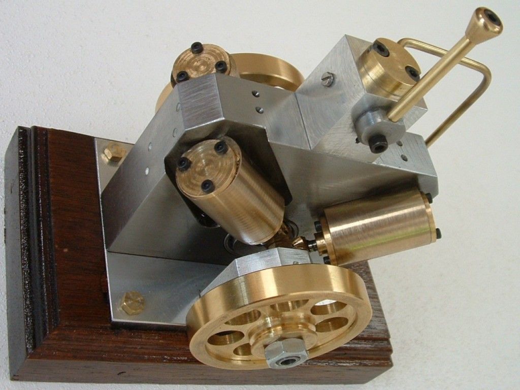
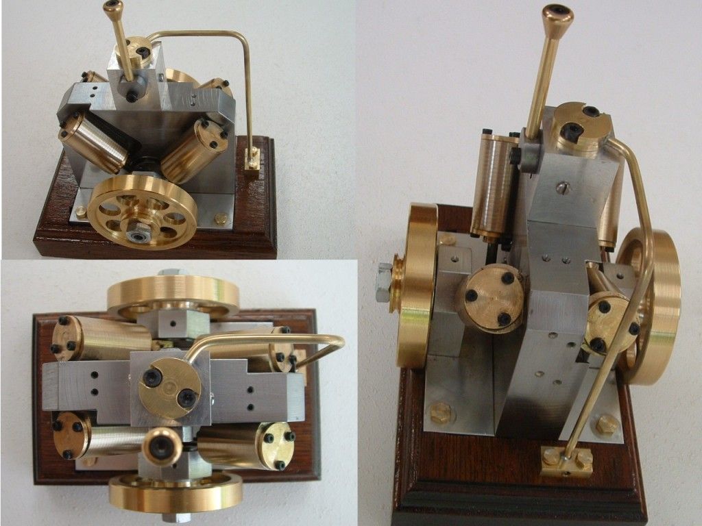
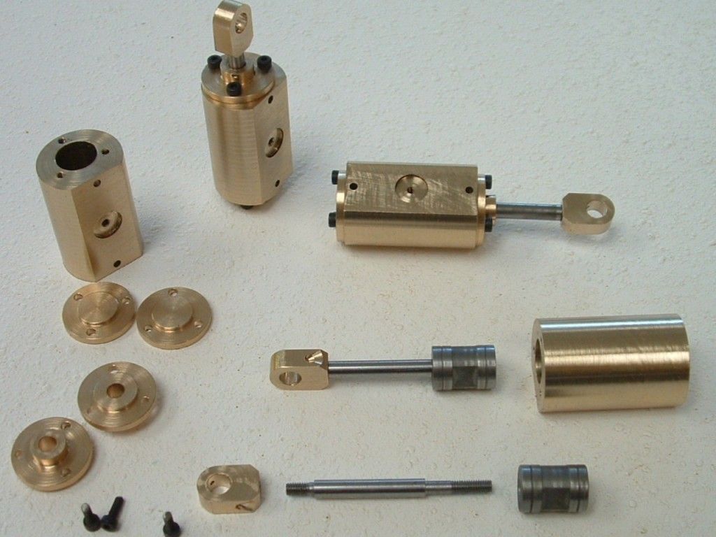
Got the four cylinder assemblies finished.
cylass.jpg

I "cheated" the three drilled holes in the cylinder heads by simply placing them on the cylinder at the last drilling & tapping position (last post) and spot drilled the head in-situ. I then drilled the spot 2mm on my drilling machine and returned it to the cylinder - fitted it in place with a M2 cap screw, 120° out and spot drilled the next hole etc. etc. - saved on having to mount and pitch drill each one.

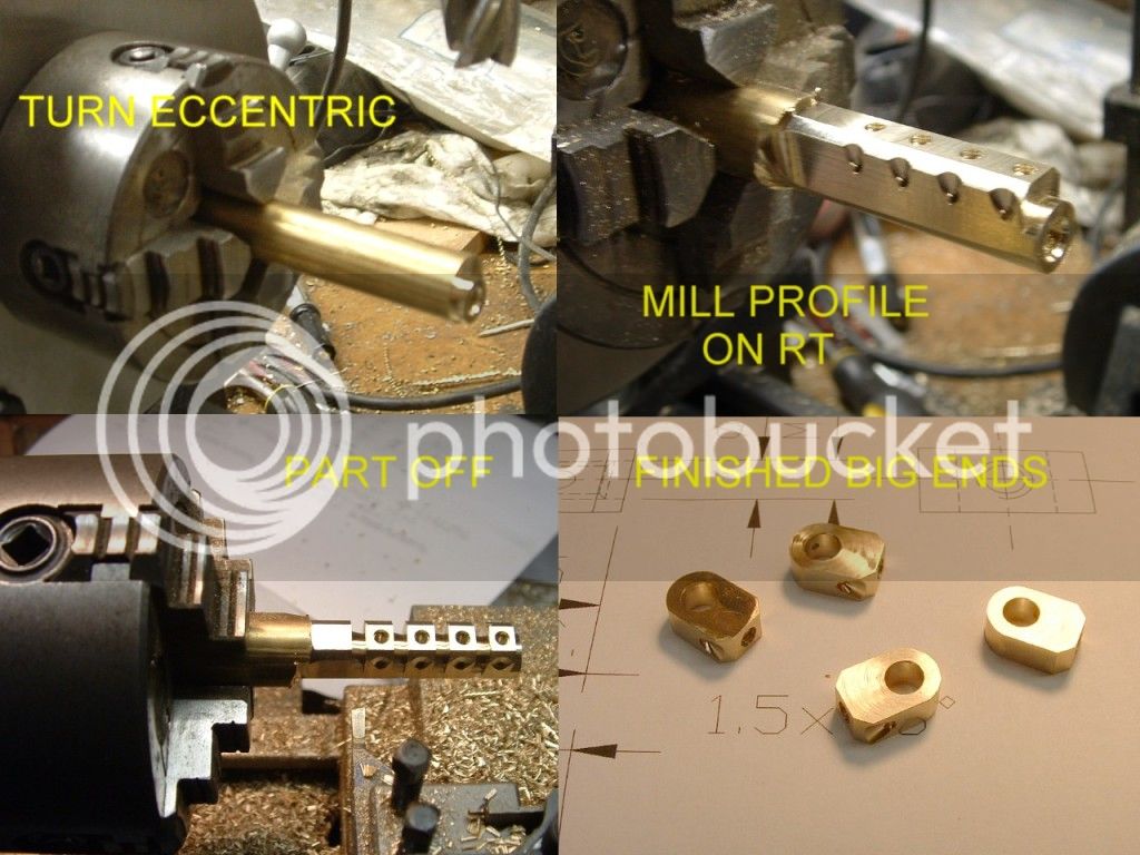
Made the big ends from the smallest barstock possible by first drilling and reaming the bore eccentrically on the lathe with the 4 jaw.

bigends.jpg

Then transplanted the 4 jaw to the rotary table and milled the profile and drilled the holes. Back to the lathe for parting off.
conrod.jpg

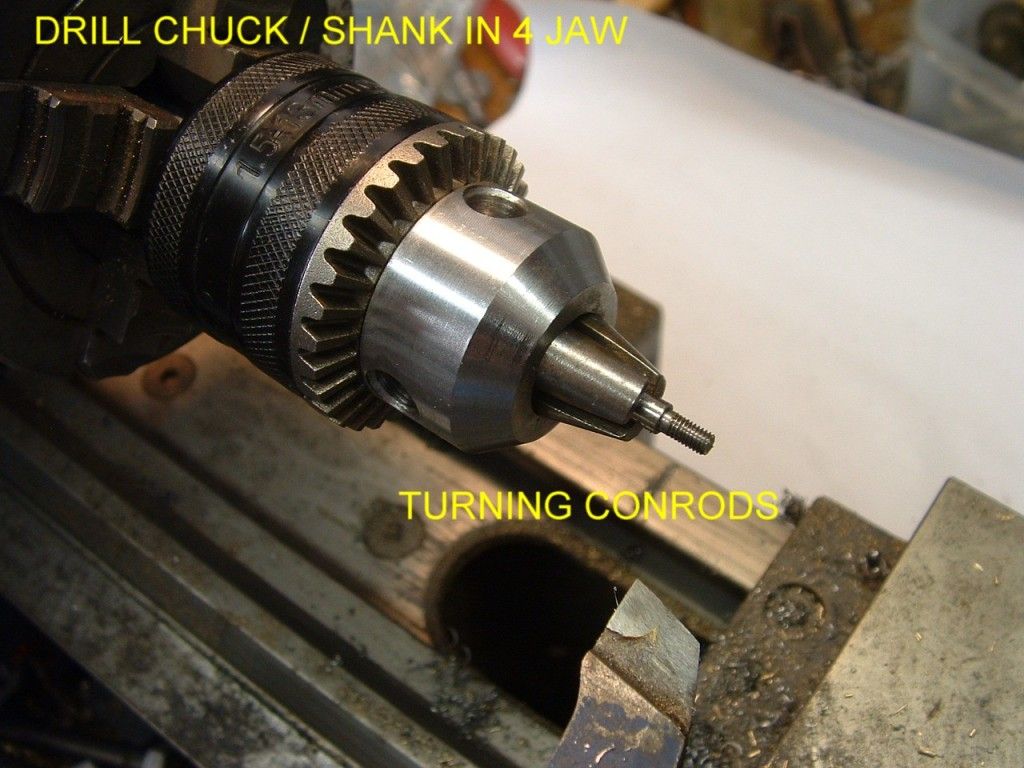
Since I don't have an ER collet chuck I turned the rods in a drill chuck I have mounted on a shank (an old shockabsorber rod which has the correct 1/2"20 UNF thread - practically made for the job) mounted in my 4 jaw.

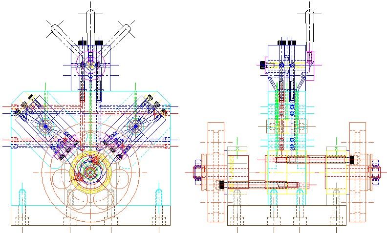
Next job the main body which is a maze of cross drilled holes.

Ken
This is almost 10 years later from your post. Do you have an ER chuck now? The ER chucks are one of my priorities. I have finished an ER 25, am currently finishing up a 32 and have the stock ready for a 40 and a 50. I just discovered the 50 and bought the nut but had a difficult time finding any actual collets. Found some expensive ones--ones that retired person's budget cannot stretch to--then finally found a single vendor with "China-like" prices.
 
The main body is mild steel with bronze bushes for the trunnions, the magnet is a press fit in the bronze to help isolate it magnetically from the body.

The drilling will also be tedious and I will need to be very carefull at the breakthrough points - I'm thinking of pushing a wire through the cross hole to prevent snatching as the drill goes through.

Anybody got any comments on that ?

Regards,
Ken
Have you eveer taken apart an old hard drive and retrieved the magnet? There is a metal, must be glued, I suppose, that is about 2mm thick on the magnet. The odd thing is that the magnetism does not penetrate that metal. So one ends up with a magnetic part that is magnetic on one side only. (To this point, I only knew about one material which is "anti-magnetic", which I thimk is Bismuth, used to be about 60$/kilo.) I'm thimking, one could use a piece of that metal, maybe, to isolate the magnets from the iron or steel. Might work.
 

Latest posts

Back
Top