V-TWIN---MAYBE V-4

Home Model Engine Machinist Forum

Help Support Home Model Engine Machinist Forum:

This site may earn a commission from merchant affiliate links, including eBay, Amazon, and others.
No, actually it was a twin cylinder snowmobile set-up, and it worked really well. Since the ignition is really a separate thing from the machined engine components, I haven't given it a lot of thought. If I were to incorporate a distributor that would direct which sparkplug the spark was going to, I could get away with one coil. This summer my main goal is to machine and assembly all of the engine components, then worry about the ignition after the engine is built. I may be getting the horse ahead of the cart here. I do have an extra 12 volt coil kicking around, and I do know I can make this system work with two sets of points and two coils, with no distributor required.
Just for a comparison: I ride a Moto Guzzi V-twin V50II (from 1979). It runs a redundant spark arrangement without any problems. Quite simply, it is just easier and simpler than having a distributor. Using a SINGLE coil with a pair of HT cables is common for motorcycles that run redundant spark. The voltage goes from HT cable 1 to HT cable 2. When Cylinder 1 is approaching compression, with gas n air at near full compression, the spark at 1 uses most of the volts across that spark gap, then through the engine, and uses the last "10%" of volts to jump cyl 2 plug to the HT lead - which is not at compression, so doesn't fire. Then the similar action occurs when the cam and points fire again for the timing for cyl 2 to fire. Simply, it just works, so don't worry about "how", just do it. A single points cam with 2 "firings" is needed, from 1 camshaft. The single low tension power then fires the "double-ended" single coil single coil, with an HT lead to each spark plug.
Good stuff Brian.
K2
 
Hi Brian, "my 0.094" slitting saw blade (which I cut fins with) was dull as a hoe"... I bought a diamond "file" - only 1/4" wide, and meant for sharpening kitchen scissors and the like. It sharpens all my tool - for lathe, Miller, etc. if the edge is just "dull"... 1 or 2 strokes per tooth should restore the teeth on the slitting saw blade. And may be easier and cheaper than a new blade?
For use on Brass, I would want a finer tooth and faster cutting speed (perhaps?) than for aluminium? But I'm sure you have all the tables to decide the correct tool.
K2
 
Just for a comparison: I ride a Moto Guzzi V-twin V50II (from 1979). It runs a redundant spark arrangement without any problems. Quite simply, it is just easier and simpler than having a distributor. Using a SINGLE coil with a pair of HT cables is common for motorcycles that run redundant spark. The voltage goes from HT cable 1 to HT cable 2. When Cylinder 1 is approaching compression, with gas n air at near full compression, the spark at 1 uses most of the volts across that spark gap, then through the engine, and uses the last "10%" of volts to jump cyl 2 plug to the HT lead - which is not at compression, so doesn't fire. Then the similar action occurs when the cam and points fire again for the timing for cyl 2 to fire. Simply, it just works, so don't worry about "how", just do it. A single points cam with 2 "firings" is needed, from 1 camshaft. The single low tension power then fires the "double-ended" single coil single coil, with an HT lead to each spark plug.
Good stuff Brian.
K2
Steamchick:
The system you describe is "wasted spark". But as you noted in your last sentence, it requires a double ended coil (no ground reference). Brian can't do that with one "standard" coil as he plans. The easiest solution would be to purchase a wasted spark (double ended) coil from a modern car. It would be cheaper than two single coils and less clumsy.
Then there is still the issue of valve timing and where each cylinder is in it's cycle. Only Brian can answer that based on his design. i.e you wouldn't want to fire the non-compressed cylinder on it's intake stroke.
 
When I built my compressor engine I bought a snowmobile coil that was for that purpose. The cdi systems we use for the mini engines had no problem getting it to fire. Fond them on Amazon or ebay. They were dumping old stock and were less than 10 bucks. Maybe see if they are still out there. Pretty sure they did not work at 12 volt so make sure it is what you want.


DSCN0653s.jpg
 
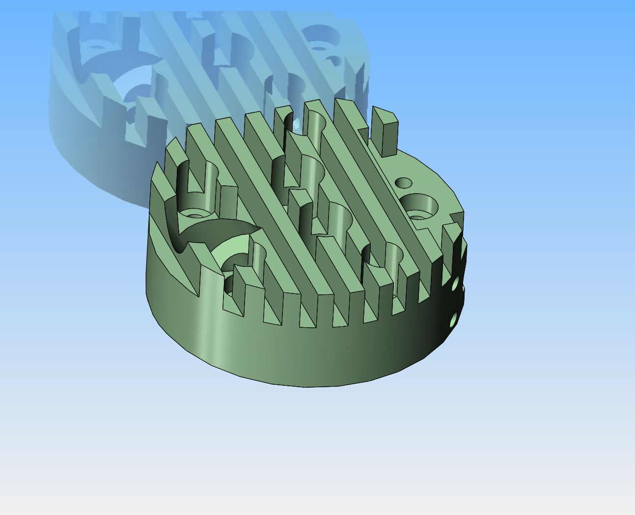
This morning before we got into birthday party mode, I spent an hour reconfiguring the cylinder head so it can be machined from a piece of 2" diameter brass. Actually, the finished part is 1.9" diameter, same as the outer diameter of the cylinder. I will look at it more closely tomorrow morning to make sure I haven't missed something. If all looks okay, then the cylinder heads will be brass.
kdYGX4.jpg
 
Animal---I know that it can be done with a single cam running in the center. I chose to do it with the double cam as I am showing it. Thanks for your suggestion.---Brian
 
    • If the hole pattern in the block and head match, just drill the hole through the cylinder. Use long screws to hold the head on that go all the way through the cylinder into the block. I have always liked the way that looks.
    • Steve Hucks--your suggestion of using long bolts to reach from the top of the cylinder head, thru the cylinder, and screw into the crankcase has a lot of real advantages. I just checked and I would need #5 socket head capscrews x 3" long to do that. Can you buy #5 socket head capscrews x that long?---Brian
 
Yes sir. McMaster Carr has #5-40 listed up to 3 inch long. If you need help getting them I can help with that for cost plus shipping with no additional fees. Let me know of you need anything.

Check grainger also. I can drive over there and get them and send them to Canada for 14-16 bucks depending on the mood of the Usps. If you get a whole box it might be more because of the weight.
 
I checked my McMaster Carr catalogue, and the 3" long shcs are full thread. Do you know of anywhere that sells them not fully threaded?
 
Why not get some leaded, 1/8" rod and make studs? You can locktite either end and have studs or bolts, I'd go the bolt route. Even if you find a source for the bolts you want, they might be$$$, esp if you have to buy a box of 100.

5/40 is my favorite thread. Material is easy to source and the pitch seems agreeable, not too fine, not too coarse!

Enjoying the build.

John
 
Vietti--a closer look shows me that I will have to save this idea for a future engine because of clearance issues. Thank you for the idea.---Brian.
 
Hi dsage: Your point "Then there is still the issue of valve timing and where each cylinder is in it's cycle. Only Brian can answer that based on his design. i.e you wouldn't want to fire the non-compressed cylinder on it's intake stroke." - is correct.
But when the mixture is right and ignition timed for the correct BTDC, then the compressed fuel-air mixture is heated by the compression, much denser than "at open inlet" and therefore ignites readily, whereas the same spark (current, not voltage) travelling across the contacts in the cylinder with open inlet valve does not have the same voltage to ionise the gases and promote ignition, the mixture is not pre-heated by compression to promote ignition, and the Stoichiometric mixture is simply not able to be ignited. - One of the reasons for a "Choke" on cold engines is to make the mixture rich enough when the "cold stoichiometric air-fuel mix in a cold cylinder" won't otherwise ignite.
Anyway, whatever the theory, I have never had a spit-back through an open inlet valve on my Guzzi... so I think it works...?
K2
 
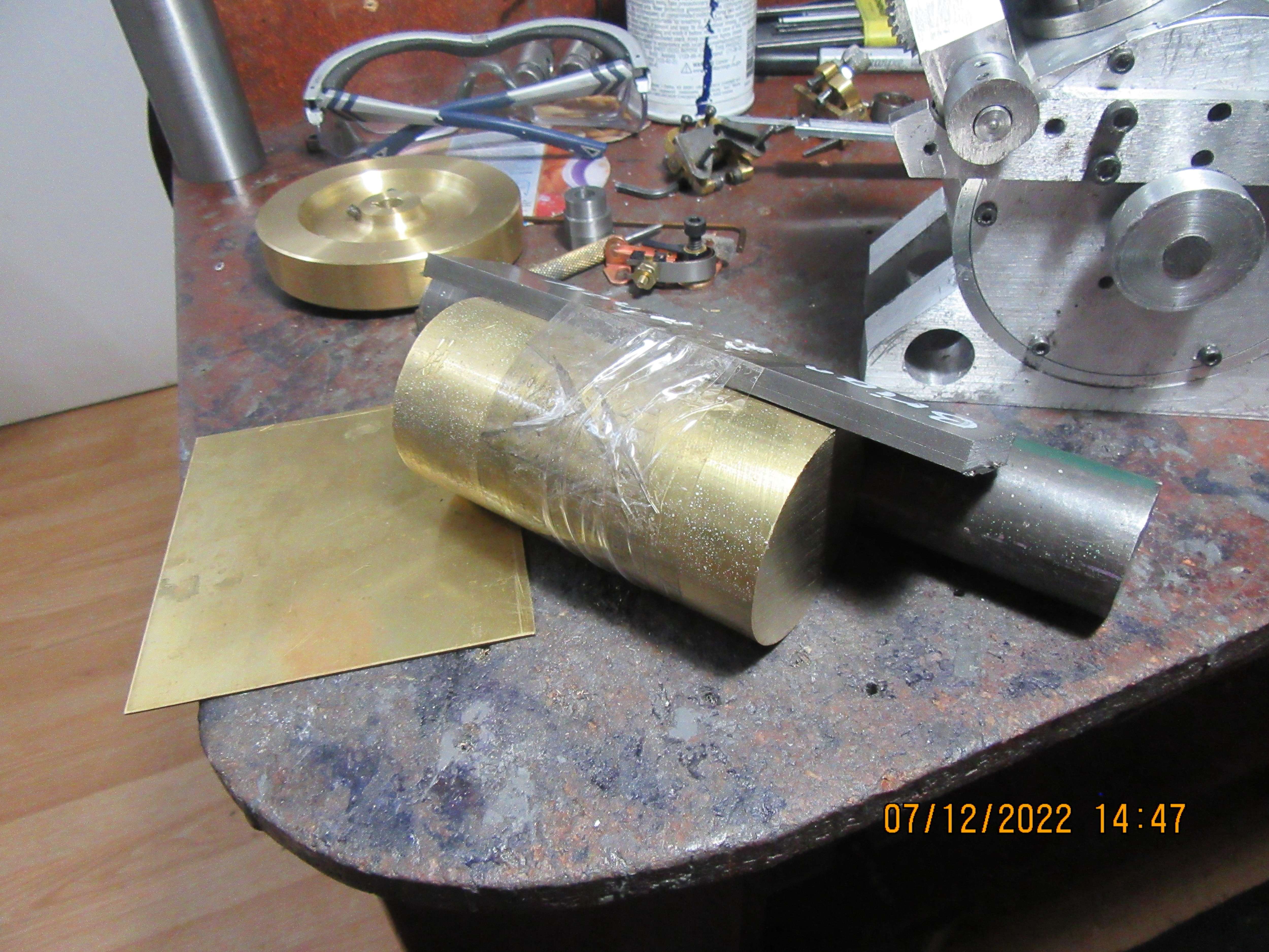
No machining progress today----But---I took a very deep breath and went into my metal suppliers and bought 2" diameter brass to make cylinder heads and gas-tank ends, a piece of 1144 stress proof to make a crankshaft, a piece of 1/4" cold rolled flatbar to make a changed ignition points bracket, and a piece of 0.040" brass sheet to cover up a machining boo boo that I made on the crank-case. That little handful of metal cost $75. I can see a time coming when I have to start making engine parts out of rocks or something.
mv6HIl.jpg
 
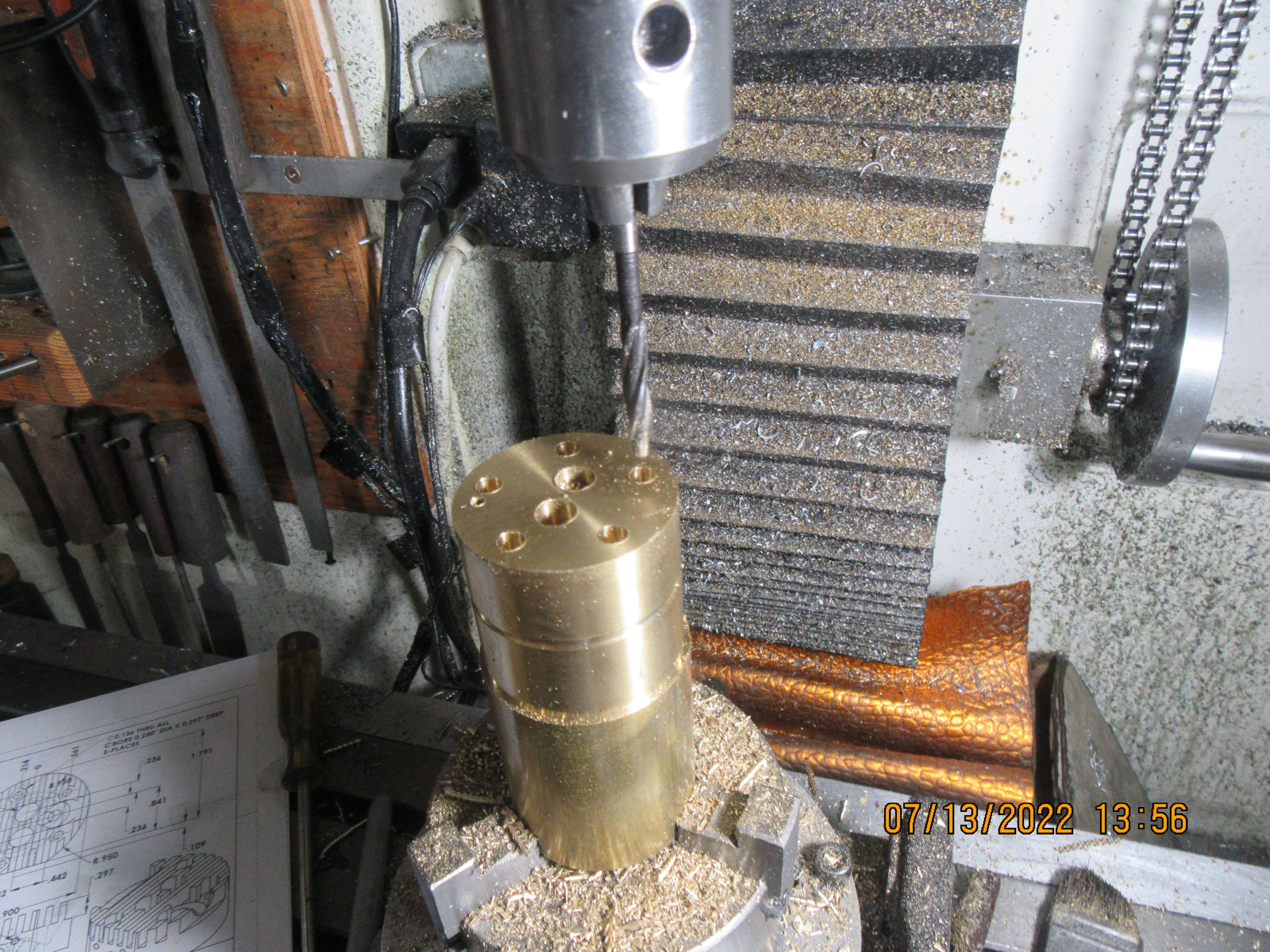
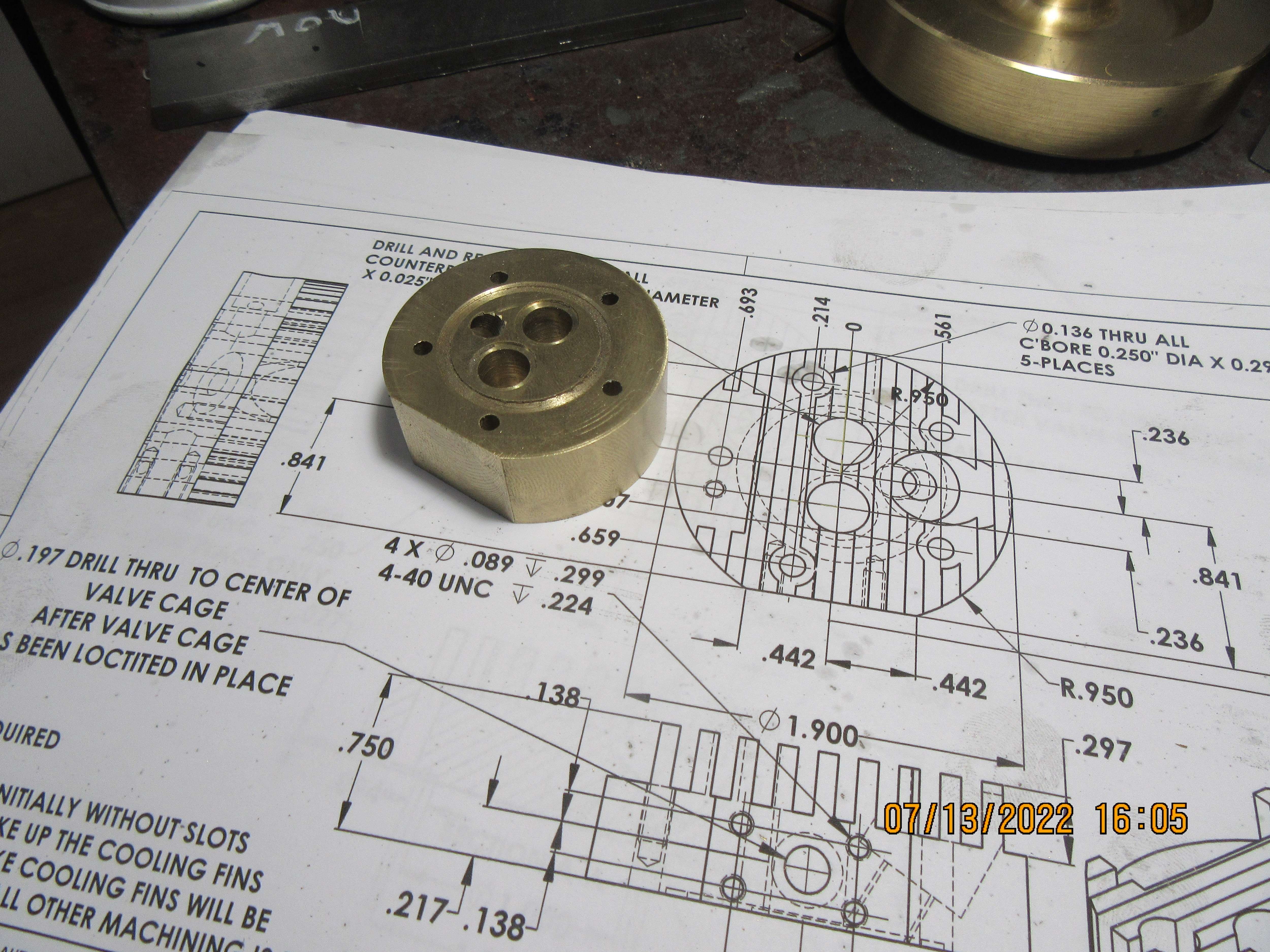
So, here we go!! Cylinder head machining step one. The two inch diameter brass has been turned to 1.9" diameter, set up in the rotary table 3 jaw chuck, zeroed out under the quill, and all of the holes drilled .8125" deep. (The finished head thickness will be 0.75".) The holes for the #5 shcs have been counterbored 0.297" deep, which is the same as the depth of the cuts between the fins. The valve cage holes have been drilled and reamed to finished size, but still have to be counterbored on the far side to accept the flange on the valve cages. One hole gets tapped #5-40 for a shcs which will eventually hold the rocker arm tower. The spark-plug hole will be drilled and counterbored in a future step, as will the flat on one side of the cylinder head. the rotary table is not being turned for these steps. It is simply acting as a holding fixture. Next step will be moving back over to the lathe to part off the first cylinder head so the radial groove for the o-ring head gasket, the counterbore for the valve cage flange and threaded hole for the sparkplug can be added.
2hj7oz.jpg
 
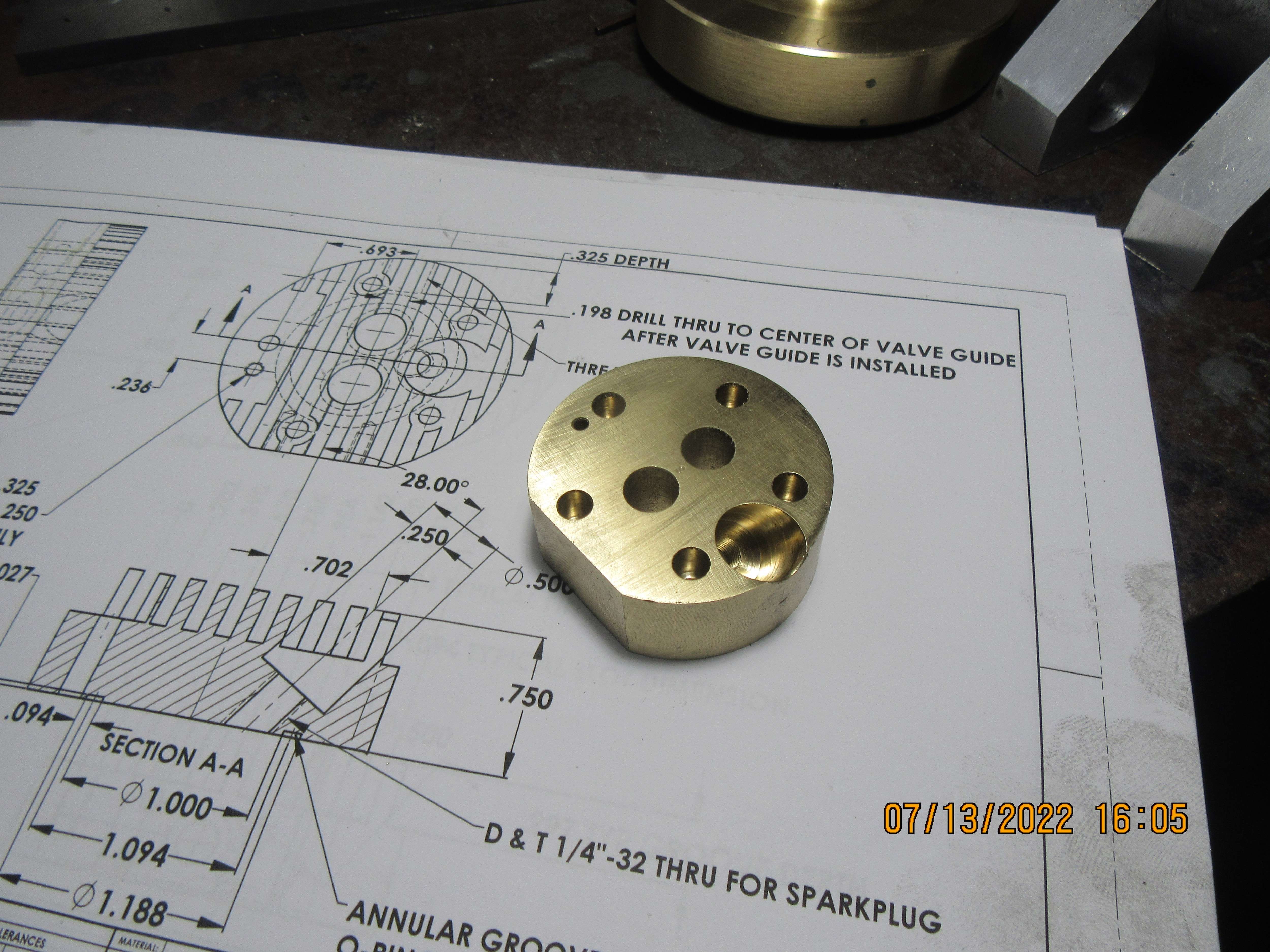
And as we get farther into it--- The counterbores have been put into the inside of the cylinder head to accept the flanges of the valve cages. The annular groove for the viton o-ring head gasket has been cut, the flat has been machined on one side to accept the intake flange, and the scariest part of all is the sparkplug hole drilled, tapped, and counterbored. This is very scary, because you are working blind. You follow all the dimensions and really, really hope that it breaks thru in the correct place, inside the annular groove and clear of the valve cage counterbores. The holes for the intake, exhaust, and intake flange won't be put into the head until the valve cages have been loctited into place. Tomorrow I get to do this all over again, only opposite hand.
M0MmWh.jpg

enEB46.jpg
 

Latest posts

Back
Top