Unusual variations on two-stroke head design.

Home Model Engine Machinist Forum

Help Support Home Model Engine Machinist Forum:

This site may earn a commission from merchant affiliate links, including eBay, Amazon, and others.
This guy seems to know a lot about modifying transfer ports and timing... May be of interest?

K2

https://vannik.co.za/EngMod2T.htm
I will be getting a copy of engmod2T and will be working with that.

This allows engine simulation, and shows the effects of changing engine features.

I quite like some of the changes "2strokeStuffing" has done.
I will watch the video you have referred to.

The interesting features I would like to consider are:

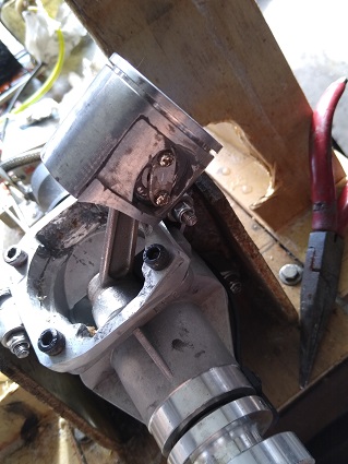
1) how to support the upper and lower halves of the barrel when they are filled with ports.
Are the blades between the ports also the main barrel supports?
Should the exhaust and outer ports shell be part of the supporting structure?

If these are changed, will the barrel still line up enough?

What gear do I need to rebore it? How do I remove the nikasil? Can I just farm out some operations?

Will getting nikasil in a weld make for a poor weld?- you are alloying in extra nickel.

2) can I space out the base studs more on a standard engine?. Can I lift the deck join up and widen it?

3) can a water-cooled barrel be reworked by tig welding it? - if it is made from 4032 eutectic aluminium-silicon, it is
low ductility, and probably needs preheating, and maybe a careful choice of filler rod.

4) can I weld in new sections of port straight on to an existing water jacket?- and still hold water?

5) do I need to buy a heat treat oven or a pottery kiln to stabilise the welding?

6) can I add a "water" cooling circuit to the lower barrel, under the "teacup" port layout?

7) will an "always open" inlet work using an existing crankcase? Does it need an extended carb tube?
Can the carb be in the middle of the tube? What theory and formulae apply here?

The structural problems are the most important. I think actual port layout examples are available.

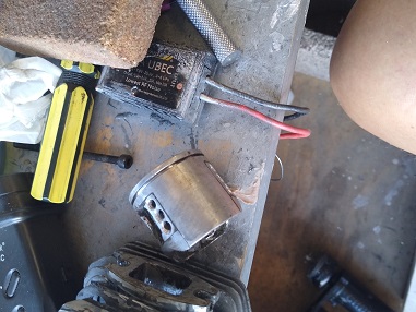
Possibly a feature could be designing a 360 degree skirt piston that bolts together.

I need to buy a fair bit of expensive gear before I can do anything like this- lathe, mill, tig welder....

Maybe an $800 usd angle-tip port-grinder set?? - there doesn't seem to be any cheap stuff around that is good for ports.

- I just whip the back off the transfer ports, and glue new backs on using J-B weld - it works well.

Special bench grinder just for tungsten tips?


I could buy the engine and just strip it, measure it, and work out some alterations before that.
The engine I have my eye on does not really support high-grade porting, hence all the alterations.
 
Here is the style of barrel I would like to work towards<image>
it is from the "2strokeStuffing" series of videos.
Notable points:
1) wide-spread base studs; - maybe M8?- however, m6 would be sufficient, and only 5 x m6 in the head.
2) wrap-around exhaust manifold built into the barrel.
I would not have such a long exhaust extension, but have an earlier assembly break line.

I an also interested in exhaust stacked over inlet, with the exhaust being half height, about 200 degrees around the cylinder, and
inlet ports around 360 degrees of the cylinder.

I think this could be practical to build, with substantial between-port webs added before cutting the main barrel supports.
these can be narrowed to about 4mm inside the barrel.
the exhaust manifold takes the form of 2 scroll cases, one each side.
Inlet flow is still biased to the cool side.

Possibly a horizontal web needs to be added and integrated into the nikasil coating.
A down-side is that crank-case volume tends to be larger, to feed all the inlet ports.
there would be 2 inlets front and back, around 65 degrees wide, with the rear port at a higher angle, and the front port around 20-25 degrees.
there would be two more side transfers each side, around 60-65 degrees, and exhausts in 3x 65 degrees and 2x a little narrower, to add to 210 degrees including dividers.
another issue is: heat transfer into the top of the transfers- should a thin water- passage area be included?
: will the exhaust reflection work well with a) all ports the same height; b) ports at different distances from the exhaust chamber??

Similar layouts have been tested in simulation. I will have a go at simulating this.
The idea with port widths is the keep all vertical webs lined up for good barrel support. They can diverge in shape, further away from the barrel.
This also allows a complete ring in the "teacup inner" transfer port shape, for a water passage.
The barrel has to be jacked up a bit from the flywheels to allow free transfer access.- you don't want barrel cutouts.
This may require a slightly different piston-pin location, or a longer rod.

I think mounting cheese-head socket screws sunk into the piston top would be acceptable, and the piston pin mount would be a separate piece.
Retaining rings would not be needed, as the pin would bear against the inside of the skirt.
 

Attachments

  • 50cc bolts, stub, port extension.jpg
    50cc bolts, stub, port extension.jpg
    38.6 KB · Views: 60
My attempt at bushing a piston to a smaller pin size is coming along.
I am not sure whether this will work ok, now.

I wonder how thick the actual piston crown is? If I have 8mm, I can recess m5 hex socket screws into the crown, and make a component to
hold the piston pin more securely.

My current Micro-lathe is not up to making an entire piston with crown, ring grooves, skirt, and inner recess.

I will carry on with the current bushed setup.
The pin and bush are not fully supported by adequate material in the piston pin boss, and the boss may
shatter.
1.5mm may be a bit low for the bush walls if they are overhung, too.
I also haven't found nice spots to put the m3 screws holding the side retainers on.

I have fitted one bush, but it is not in deep enough, so I will push it out again once I have bored the other side to 13mm- actually around 12.9mm.

Once I have both holes bored slightly undersize, I can ream them as a pair to improve alignment, and I can also ream both final holes as a pair.

Any change in overall squareness to the piston will be minimal, - in the order of 0.2 mm over 35mm, or 1 in 175, 0.3 degrees.
I will finish it off, run it, and inspect it for damage. I have a spare piston and barrel off a slightly different engine if I trash this set.
 
Hi Owen, re: "I wonder how thick the actual piston crown is? If I have 8mm, I can recess m5 hex socket screws into the crown, and make a component to hold the piston pin more securely. "
If the crown is very thin, you can consider a nut-and-bolt arrangement, if you use countersunk screws in the crown, as these are reasonably easy to seal (cone in cone) - even maybe a drop of Loctite or silicon sealer will survive the alloy temperatures? The nuts on the underside of the crown/part you are installing to reinforce the pin bosses can then take the tensile load of the assembly, without risking femur threads in the crown?
Or maybe I misunderstand the item?
Cheers!
K2
 
Hi again Owen. Can you clarify the small end arrangement? The industry standards (if I remember correctly!) are either a pin fixed in the piston and small end bearing in the rod (so called "floating pin"), or a pin fixed in the rod and the piston pin bores become the bearings for the small end motion (so called "fixed pin"). My experience of 2-stroke engines has only been "floating pin" types, often with needle roller bearings to reduce heat loading here (the nomenclature relates to the con-rod joint). Bosses are basically the same strength, but different finished sizes for the applications. I guess that you are going to a smaller pin - fixed in the piston - with bearing in the con-rod?
K2
 
Hi Owen, re: "I wonder how thick the actual piston crown is? If I have 8mm, I can recess m5 hex socket screws into the crown, and make a component to hold the piston pin more securely. "
If the crown is very thin, you can consider a nut-and-bolt arrangement, if you use countersunk screws in the crown, as these are reasonably easy to seal (cone in cone) - even maybe a drop of Loctite or silicon sealer will survive the alloy temperatures? The nuts on the underside of the crown/part you are installing to reinforce the pin bosses can then take the tensile load of the assembly, without risking femur threads in the crown?
Or maybe I misunderstand the item?
Cheers!
K2
the underside of the crown is hollowed, but I can machine that more smoothly and add a domed plate.
Thank you for the suggestion. I will have a look for grade 8 hex socket head countersink screws, and order some.
 
Hi again Owen. Can you clarify the small end arrangement? The industry standards (if I remember correctly!) are either a pin fixed in the piston and small end bearing in the rod (so called "floating pin"), or a pin fixed in the rod and the piston pin bores become the bearings for the small end motion (so called "fixed pin"). My experience of 2-stroke engines has only been "floating pin" types, often with needle roller bearings to reduce heat loading here (the nomenclature relates to the con-rod joint). Bosses are basically the same strength, but different finished sizes for the applications. I guess that you are going to a smaller pin - fixed in the piston - with bearing in the con-rod?
K2
No, this is a conventional 2-stroke top end, with needle roller in the centre. The pin is standard, retained by wire circlips.
The problem is the RC model engine uses a smaller piston pin diameter. I can make a smaller cage "piston" that fits inside a larger outer piston, and remove
everything outboard of the piston pin end. there is about 4mm further to the cylinder wall each side. This can have enough material to thread to take the crown screws- about 10mm thread should do.
 
I was successful with my second go at putting stepped bushes in a piston.
This one has better bosses tor my app.

However, the piston skirt is too narrow to cover the exhaust port, and the ring locating pin enters the inlet port, so I will try some addons with J-B weld.
I will get to see if the surface adhesion and peel holds up with heat and oil.
I think the J-B is porous to oil.
Previous use on piston inserts and transfer buildup looks promising.
I don't think we will get the full 18 MPa working load.
UTS is 24 MPa. I haven't worked out the relative volume of aluminium I can support with various lengths of J-B Weld joints.

I will look up the acceleration formula, and try and work out some stresses. rpm will be limited to 8000 rpm max, so average piston speed is below 12 m/s.

I have ordered a couple of carburettors for future use on a watercooled engine.
A PWK 30mm and a PVK 32mm
they are copies of Keihin carbs, but were quite cheap.

The PWK is a flat-slide type, and the PVK is a constant velocity carb. I want to extract the butterfly section for the inlet reed valve bypass, or inlet power valve.
 
Piston peak acceleration:

This is in the order of 16,142 m/s(sq) or 1647g at 8000 rpm, 36.5mm stroke.
This is proportional to the square of the rotational speed.

I derived this from plots on Wikipedia for 3.6" stroke giving 2.3 inches/rad(sq) acceleration.
This is actually at the top of the stroke- bottom stroke acceleration is a bit less.
The bottom acceleration is the worst loading case, being partly tensile, and mostly shear.

Typical hanging part = 24x10x2 = 1.3 grams.
glue area = 10x2mm
f= Ma = 16,142 x 1.3 x 10**-3 = 21N
stress = f/a = 21/20 x 10**6 = 1 MPa.
This is acceptable. - up to 18 MPa is allowed under ideal conditions.

Actual glue area is along the top in tension, plus down the side at 24x1.5 mm, so load on the glue appears to be sustainable.

We shall see if the effect of heat, oil, and cycling load, will undermine the adhesion.

Actual component prep is OK, with basic degreasing with acetone wipes, roughened by Dremel/milling cutter, new parts.
Light sand blasting would be better.
thrust and impact loading should be fairly isolated from the add-on parts.

I have also transferred the bridging parts at piston radius, under the boss, from one piston to the other. This is to avoid having corners of the
addon wings hanging free, and takes some potential load off the glue.
 
The engine seems to run OK.
No sign of things coming apart, and performance is on par with the original and modified TP parts.
I now have to get my optical rev-counter running properly again.- recharge the batteries, paint a white patch on one prop blade?
I will do a disassembly check after an hours running.

I accidentally fouled the propeller with the cam-out starter, and smashed all my engine mounts. No injuries.
You have to be careful about leaning in to the starter, and it is in a poor position, below waist height.
The prop was a bit dinged, so I swapped it for a lower pitch prop. The restart went well, after a carb cleanout.
I added two boost ports, but of a more sensible size than the original, with smaller piston holes. This should wear better than the original.

It doesn't seem to matter about the extra side holes in the piston.
I thought that the vent holes for the boost ports would help with circulation under the piston.
125 motocross engines seem to have no under-piston venting at all.

here are some photos of the parts:
 

Attachments

  • IMG_2022-05-21_5.jpg
    IMG_2022-05-21_5.jpg
    55 KB · Views: 33
  • IMG_2022-05-21_4.jpg
    IMG_2022-05-21_4.jpg
    57.4 KB · Views: 36
  • IMG_2022-05-21_3.jpg
    IMG_2022-05-21_3.jpg
    50.9 KB · Views: 36
  • IMG_2022-05-21_2.jpg
    IMG_2022-05-21_2.jpg
    50.5 KB · Views: 38
  • IMG_2022-05-21_1.jpg
    IMG_2022-05-21_1.jpg
    57.7 KB · Views: 38
progress report: sudden suspicious stoppages.
I pulled it down, and there is no obvious seize marks, but higher than normal bore wear than expected, including the ring area.
It just looks polished, with no scoring.
I am presuming that the engine cannot do without the side vents, so I have added some - see photos.
I also put the screws back with red Permatex thread lock- they were not as tight as expected.

Possibly air-cooled two-strokes need more under-piston venting. - any history on this? The Suzuki 50s don't seem to have any side vents
<Edit> yes, the 41mm bore Suzukis don't have vents. I had an AC 50 as my first bike, and it has no piston vents.
Maybe it is a feature of the 45mm bore engines??
There is a double hit of more top area to absorb heat, and less piston skirt to dispose of heat.
 

Attachments

  • IMG_20220523_2.jpg
    IMG_20220523_2.jpg
    50.2 KB · Views: 34
  • IMG_20220523_1.jpg
    IMG_20220523_1.jpg
    50 KB · Views: 37
Last edited:
We are back to "engines built" but I will stay in general discussion for now.
I had my first full tank high speed run.
The carb is behaving oddly, in that if I turn down the low speed mix a bit, it stalls after a while at high speed.
If I keep low speed at 1.5 turns, it rich misfires around 5,000 rpm, but runs smoothly around 7,000 rpm.
I left the high speed needle at 1.5
My tacho is playing up- it seems to flatten the batteries too much on standby, and doesn't have a positive "off".
I shall have to leave the batteries out when I am not using it.
There is a sudden engine tone change above 7,000 rpm, which I suspect is the start of transfer blowback.
I stop winding it up at this point.

I am abandoning my initial goal of smooth low speed running and gradual speed increases on the throttle, as this would need radical head changes.

Possibly the primary plug should be more recessed, and it could take a variable transfer setup. Reducing transfer area makes the engine run more smoothly at lower rpms.

I have also accidently blown up my twin-spark cdi unit, but this could just be a blasted electrolytic capacitor, which could be fixed. It is not keen on 16 volts!
I may come up with some schemes for this engine, but it is running as well as it is going to go on a prop, and without a pipe.

Any more revs would blow up my fabricated piston, and it need the prop for cooling.

I am looking at getting a cheaper 400 mm floor-type high flow blower for water cooling, but I could dunk the radiator in a big tub of water.
-a large round rubbish bucket? - I will look for one.
That could need a thermostat added to the water circuit. I will check when the other engine arrives.

I will wait to start on my water brake until the aluminium tube arrives. I will try fabrication with the aluminium solder, but to get a really well-wicked
joint may take extra wet flux, not just flux-cored rod. I can see how it stands up for strength and heat stability, too.

I also need to start collecting other materials for the dyno, and dummy up the Arduino, and the Notebook serial interface, and display/recording software.
I have an Arduino board, but I haven't had a go at using it yet. This one runs on a regulated 5V supply. or off the USB plug.
I need to look for a load cell module that is readable by the Arduino.
 
Last edited:
Back
Top