
You are using an out of date browser. It may not display this or other websites correctly.
You should upgrade or use an alternative browser.
You should upgrade or use an alternative browser.
Two Engines in One or Elmer Gets a Makeover
- Thread starter Sshire
- Start date


Help Support Home Model Engine Machinist Forum:
This site may earn a commission from merchant affiliate
links, including eBay, Amazon, and others.
Sshire
Well-Known Member
- Joined
- Jun 29, 2011
- Messages
- 936
- Reaction score
- 259
Jerry
So the air supply should be coming in opening in the side of the valve housing, not the front?
I've tried it both ways. Whatever. I've also drilled out the back crankcase cover and loctited a new bushing in because I detected a small amount of runout in the crankshaft.
Engine is now disassembled and cleaned. I need to make it a bit looser. Piston reduction begins in the morning. I'd do it now but went out to dinner and won't go into the shop after the (as I believe ArnoldB says) fine Scottish produce consumed. Heavy machinery and all that.
The radial merriment continues tomorrow.
Best
Stan
- Joined
- Dec 2, 2008
- Messages
- 971
- Reaction score
- 8
Stan
Like most air/steam engines, swapping inlet and exhaust just changes the direction of rotation. Either way would probably work, but as I was thinking about this engine, it came to mind that someone had fabricated and fitted a neat little diffuser/muffler to the axial port on the valve cover face. I can't remember whose build it was but it was a nice touch.
Jerry
So the air supply should be coming in opening in the side of the valve housing, not the front?
Stan,
now I've read the instructions, Elmer confirms that
"Drill #23 through the backwall for later tapping the 3/16-40 MTP exhaust connection", on page 44 in the valve housing paragraph.
Now, the visual check of air admission to the piston at TDC is trivial. I suppose the valve should open slightly after that moment (and have a perfect seal both on the other two admission holes and the backwall itself, having no means to take advantage of the steam pressure to gain that).
Much less an 'easy' design for a straightforwad build that it looked at first sight.
Thank You for starting this thread.
Marcello
Sshire
Well-Known Member
- Joined
- Jun 29, 2011
- Messages
- 936
- Reaction score
- 259
Marcello
I must have read that 100 times and if I recall, I started with the intake on the sidewall and then switched it to the back wall. I'm reassembling the engine now so I will check the "timing" of the outer ports (outside of the valve).
I'm also going to plug the flywheel outer edges with brass around the O.D. to get some additional mass. Elmer specs a 2" flywheel (he doesn't say, but I'm assuming steel). I had a 3" flywheel in 6061 already on the bench so I used that.
Back to the shop
Best
Stan
- Joined
- Dec 2, 2008
- Messages
- 971
- Reaction score
- 8
It is still to hot in the shop so here is some 3D model entertainment.
http://www.youtube.com/v/pm1CYaaKvE0?version=3&hl=en_US&rel=0
Jerry
http://www.youtube.com/v/pm1CYaaKvE0?version=3&hl=en_US&rel=0
Jerry
Sshire
Well-Known Member
- Joined
- Jun 29, 2011
- Messages
- 936
- Reaction score
- 259
WTF revisited
I haven't died. I haven't given up on making this run.
Progress report. Pictures later.
So I'm thinking about the movement of the valve (this valve design must have been done when the original designer was either on drugs or or thinking "Ha! This should give those engine builders fits.).
When I drilled more holes so that I could see the valve movement and the air passage holes, I was looking at the inside of the valve and everything was good. At that point the air was entering on the valve axis (the front of the valve housing.)
Then I said "Huh? If this movement is correct for the inside of the valve with air coming in the front and I move the intake (per Elmer ) to the side, it can't work. No air gets in."
Looking at the drawing of the valve crank, never having seen a set of engine plans until 11 month ago, I assume (correctly or incorrectly) that the front view is looking at the front. (What the hell did he just say?) and that the .125 hole for the crankshaft pin is on the right. So the other day, probably because I don't know any better, I figured that if I drill another .125 hole, the valving should work with the intake on the outside of the valve. It did.
Maybe problem 1 solved.
Then I was seeing some off-center movement of the crankshaft because of a crappy center hole in the rear crankcase cover. Plugged, recentered in the mill, drilled and reamed .251.
Maybe problem 2 solved.
There is some just perceptible binding somewhere. I've disassembled, filed, sanded, oiled, just about every part. I've narrowed down the binding to one 120 degree area of rotation.
I'm going back down to the shop to work on that. I still think it's the center hole in the crankcase cover even though I "line bored" it to keep it in line with the center hole in the front of the crankcase.
Any suggestions to have both holes line up "dead nuts" (another addition to my vocabulary since joining this forum)
I have pix of this entire fixing process and I'll post them once I get this binding fixed.
Stay tuned
Best
Stan
Sshire
Well-Known Member
- Joined
- Jun 29, 2011
- Messages
- 936
- Reaction score
- 259
A Runner (Finally)
More fiddling, filing, cutting gaskets, and then IT RUNS!!!
I'll be posting the final installment of this build log, or "Everyone from Florida to Italy figures out why this won't run"
Thanks again to Cap'n Jerry, Marcello, Arnold and everyone else whose input was amazing.
Pictures of all fascinating operations and troubleshooting "fixes" will be posted over the weekend, but meanwhile...
Best and Thanks again
Stan
- Joined
- Dec 2, 2008
- Messages
- 971
- Reaction score
- 8
Nice going, Stan Thm:
Nothing beats success and the harder the battle, the sweeter the victory!
Jerry
Nothing beats success and the harder the battle, the sweeter the victory!
Jerry
Sshire
Well-Known Member
- Joined
- Jun 29, 2011
- Messages
- 936
- Reaction score
- 259
Thanks again Jerry.
I really had no idea where to begin and your posts and the animation got me going.
I still have a few parts to finish: The blingy finned caps on the cylinder heads, a proper crankshaft support, a muffler and, maybe, a propeller because there isn't much to see when this engine is running.
Then a good cleaning and polish and I'll call this one done so I can start on Bill Reichart's Epicyclic Engine.
Couldn't have done this without you.
Best
Stan
")
Sshire
Well-Known Member
- Joined
- Jun 29, 2011
- Messages
- 936
- Reaction score
- 259
Thanks everyone
Oh yeah. I've got pix of the fix. Or fixes.
I'm out of town until tomorrow but will post the rest of the build pix over the weekend.
Hope to finish the head covers this weekend also. I'm going to attempt a form tool for the first time to make them. Furious polishing will follow.
Best
Stan
Oh yeah. I've got pix of the fix. Or fixes.
I'm out of town until tomorrow but will post the rest of the build pix over the weekend.
Hope to finish the head covers this weekend also. I'm going to attempt a form tool for the first time to make them. Furious polishing will follow.
Best
Stan
AlanHaisley
Well-Known Member
- Joined
- Nov 30, 2007
- Messages
- 142
- Reaction score
- 6
Congradulations Stan. I'm waiting with scratch.gif to see all of the fix choices.
Alan
Alan
Sshire
Well-Known Member
- Joined
- Jun 29, 2011
- Messages
- 936
- Reaction score
- 259
Two Engines in One - The Final Episode
The engine runs. It turns out that none of the changes to the engine (except one) were the culprit. All of the other pieces are to Elmer's dimensions. After the "customization" of the cylinders, the rest of the engine is in the "don't screw with these parts or it probably won't work" category. You'll have to wait for the the end of this post to find out the multiple causes that made this a non-runner and the fixes that made it a runner.
I'm not going to show stuff that you've seen and done hundreds (or thousands) of times, like "Hey, here's me facing a .250 rod on the lathe."
I'm going to hit things that, as a very beginning builder, I had to figure out a way to accomplish. Most of you can just page down over those things, but they may be helpful to novices like me. I've learned so much from Works in Progress that I really have a need to pass those on.
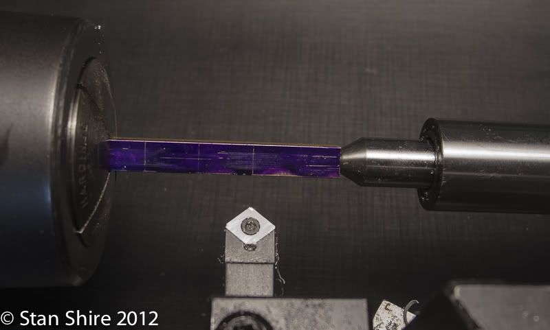
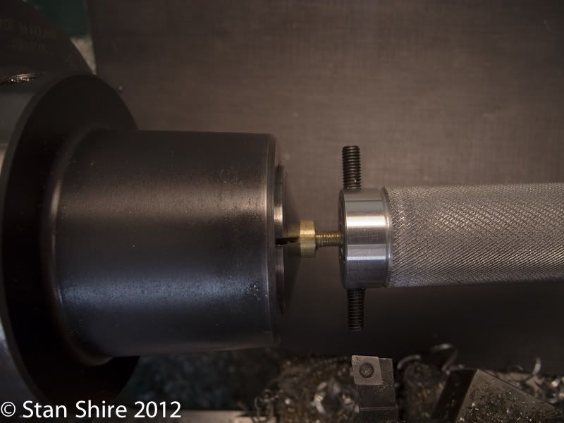
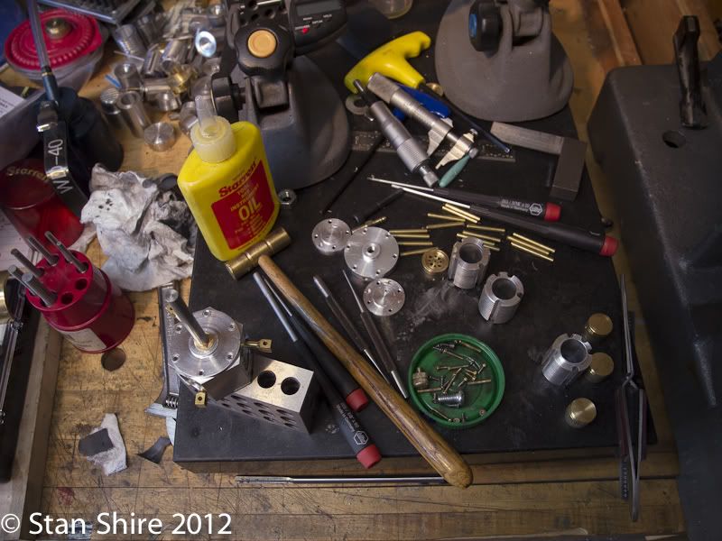
One piece of tooling that was extremely helpful was learning about the tiny live center that Bogs showed a few months back. I ordered it from ArcEurotrade and have used it a great deal. The connecting rods are a perfect example. Thanks, John.
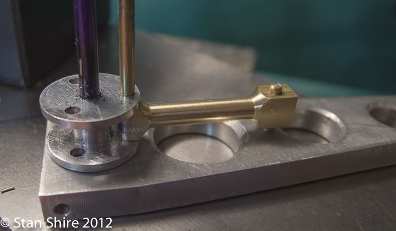
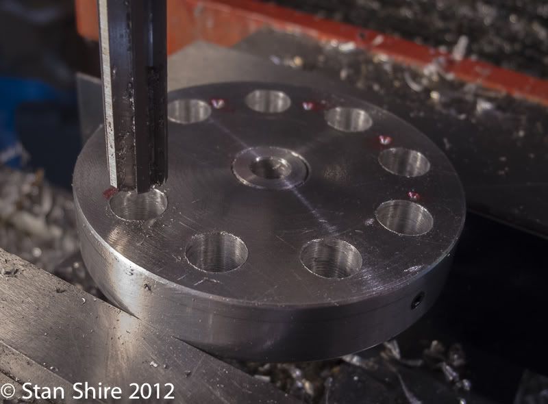
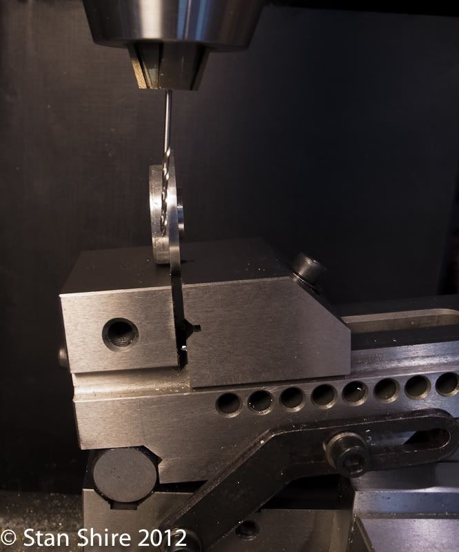
Elmer wants the fixed connecting rod to be perfectly aligned with the central hole in the hub. (he actually said "Try to make the rod centerline pass through the hub centerline.") Try? What happens if you fail to do so can't be good, so I made a fixture. If the fixture looks suspiciously like a mis-made Grasshopper part .
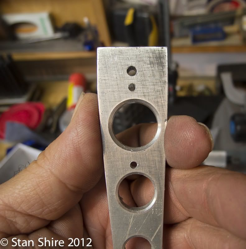
I drilled three holes (not the big ones) to match the hub center, the pin for the rod and the wrist pin hole. With those in line, a little Loctite and done. Take that Elmer!
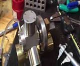
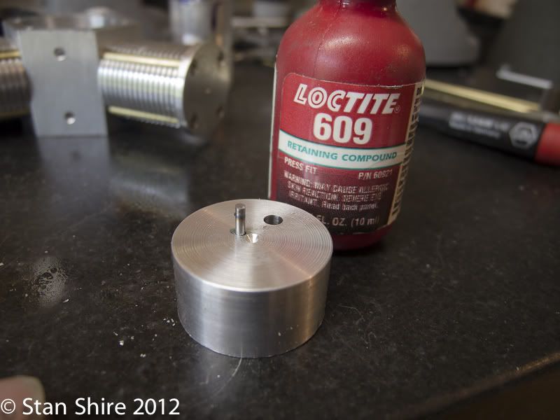
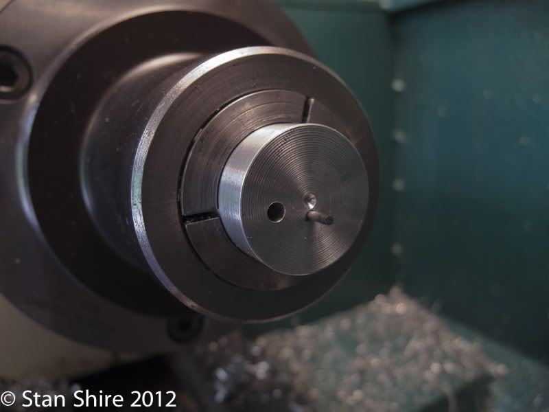
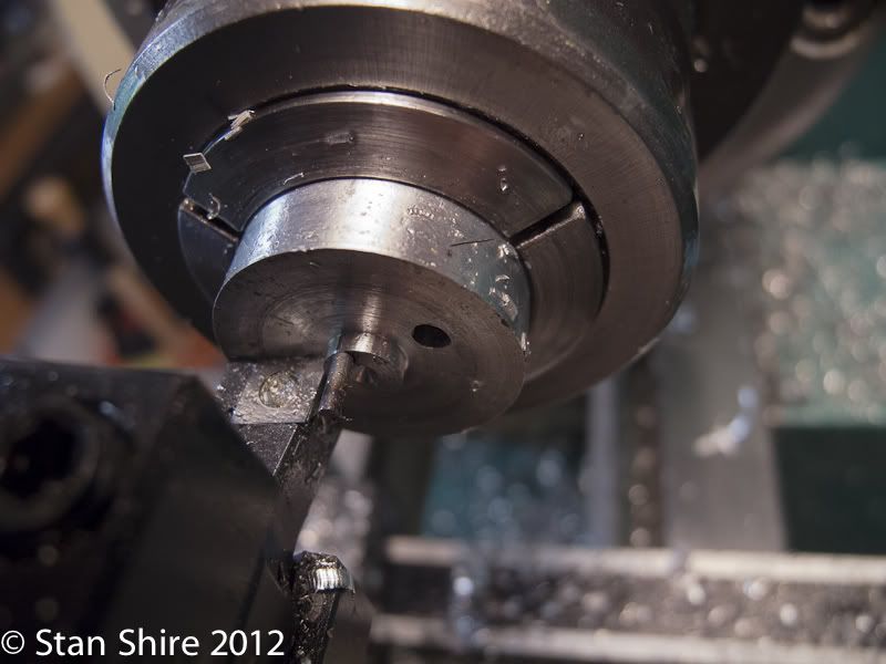
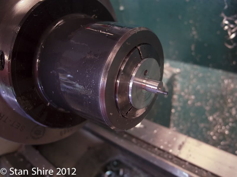
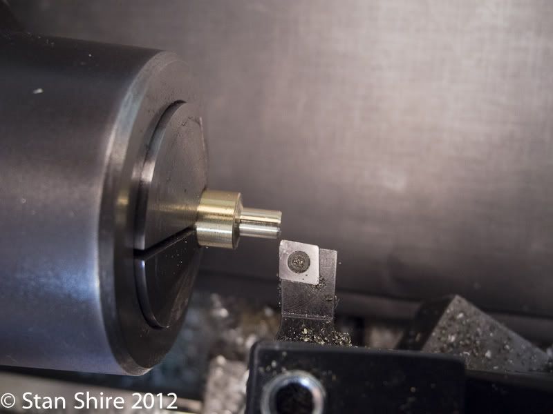
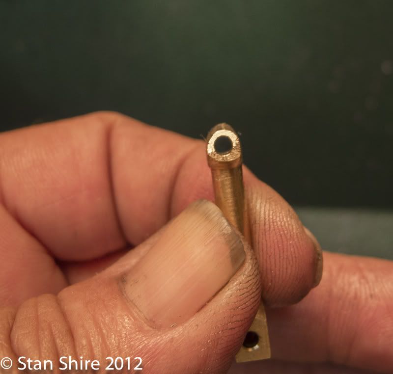
For my next trick, turning the tiny pin in the valve crank offset. (we'll be coming back to that valve crank later) Elmer sez "Do it in one piece" Not a prayer. More Loctite (remind me to check their stock price. It must go up when I build an engine). Then into a 5C collet and turn the spigot down until I can just see the pin. Precision at its best.
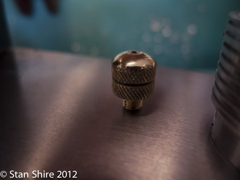
The vent plug. Pretty straightforward but I liked the way it ended up.
Turn down a piece of brass rod, thread and center drill, knurl and some lathe filing.
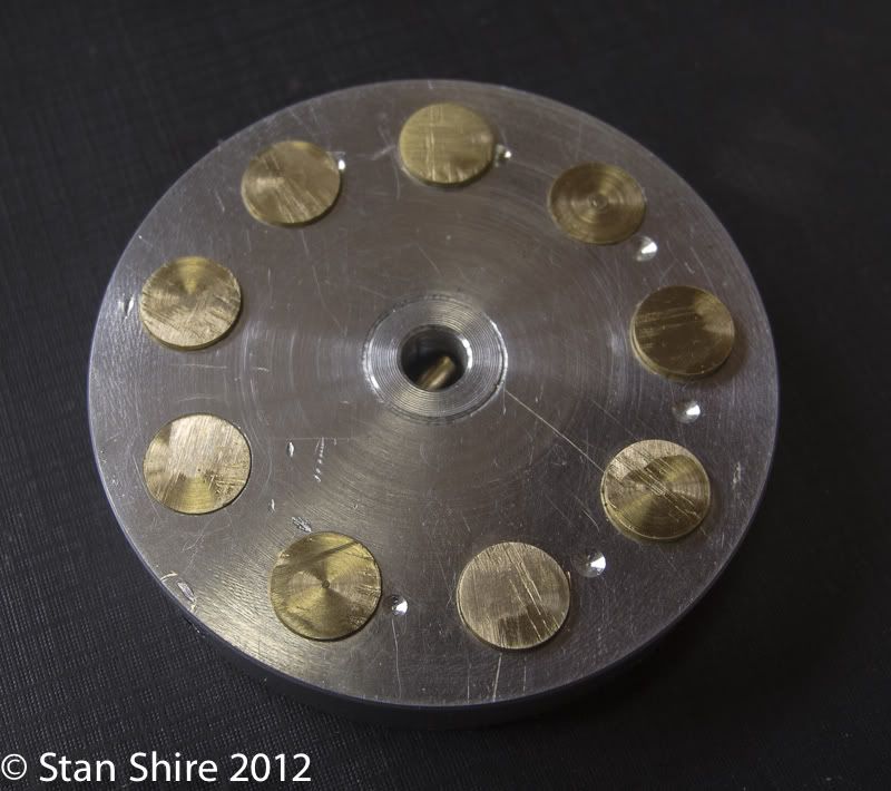
I made the flywheel from 6061 aluminum. Probably should have been brass for mass but I had none here. I later decided that additional mass at the outer edge would help. Drill, ream .375, press in brass plugs.
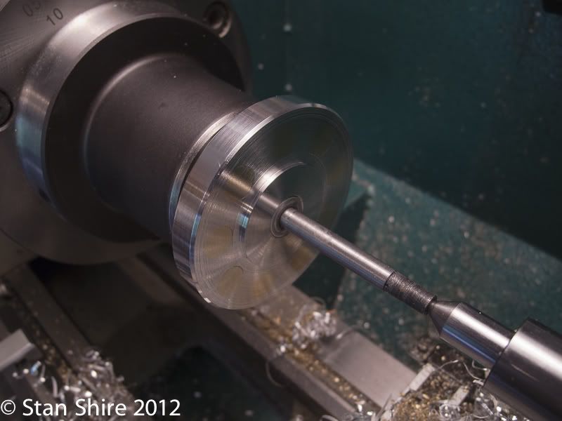
I then put the flywheel on a tapered mandrel and faced it.
The crankcase cover has an oil passage but Elmer doesn't give an angle for drilling it.
I put the small sine vise in the milling vise (only so I wouldn't have to re-align the vise) and eyeballed the entrance and exit points for the drill by eye.
Amazingly, it came out perfectly!
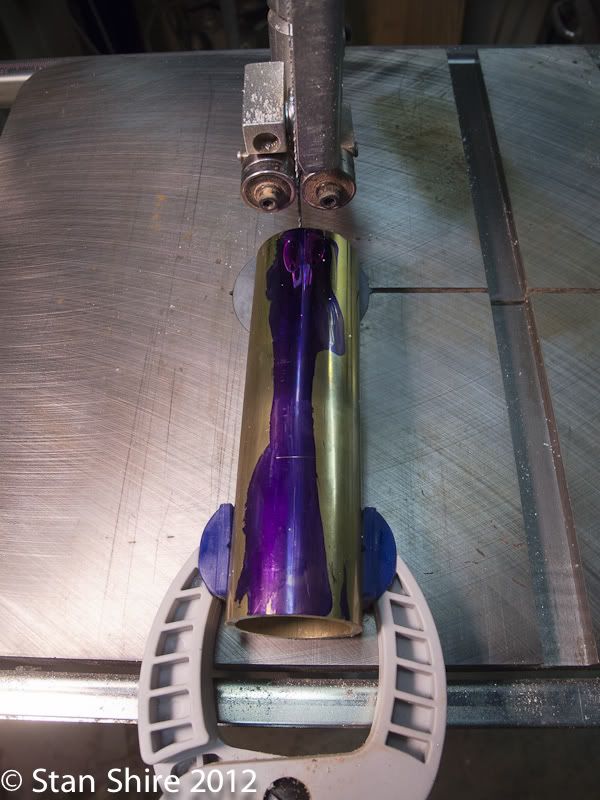
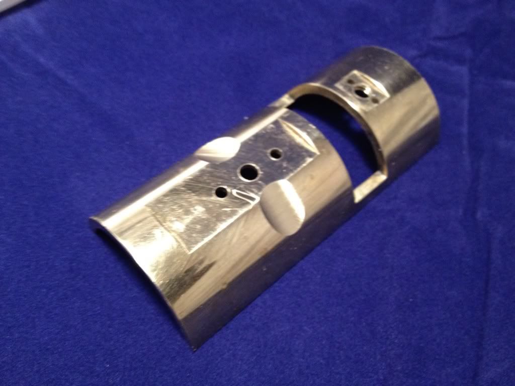
After thinking about the base for days, I came up with a half-cylinder with the flywheel recessed.
I used the height gauge to scribe a line and then clamped the brass tube to keep it stable while it ran through the bandsaw.
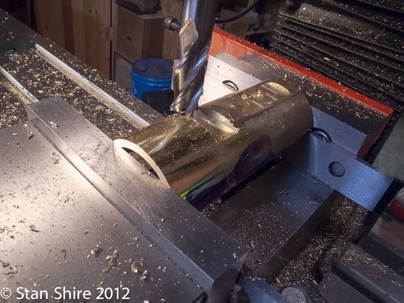
Then clamped the cut piece in the vise and face milled the cut edges to level everything up. Have I told you how much I love that Glacern 45 degree face mill?
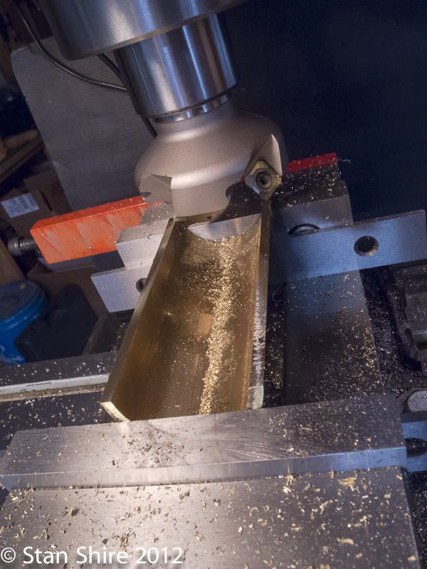
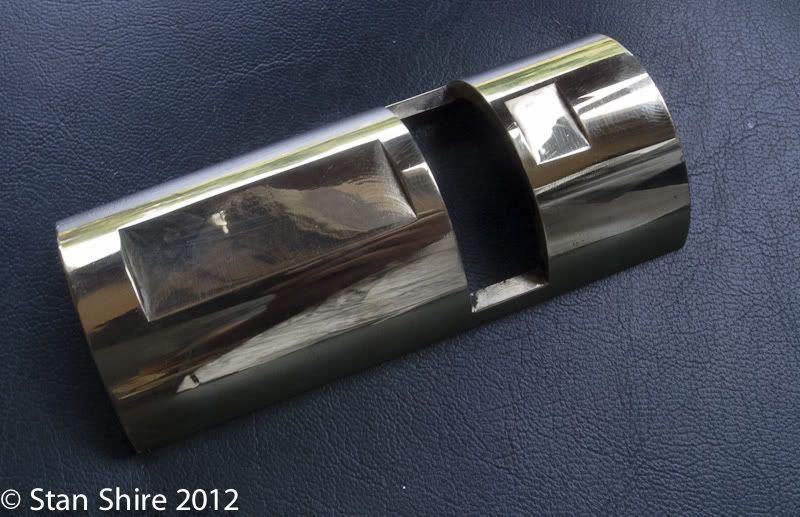
Then inverted the piece and milled the recessed for the crankcase, flywheel and rear bearing
And done. Drilling for mounting bolts ensued.
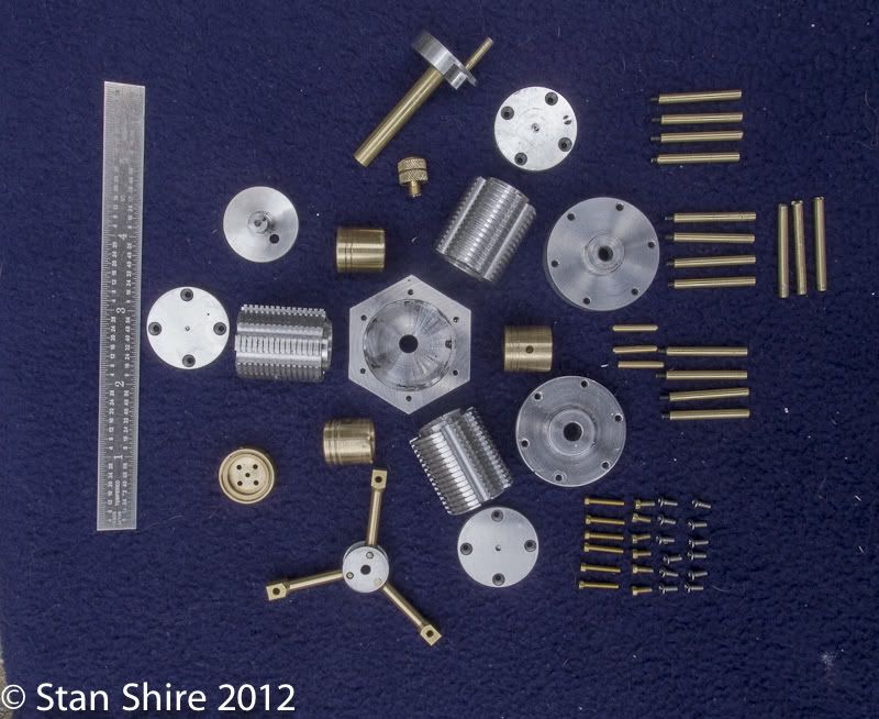
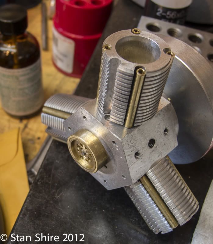
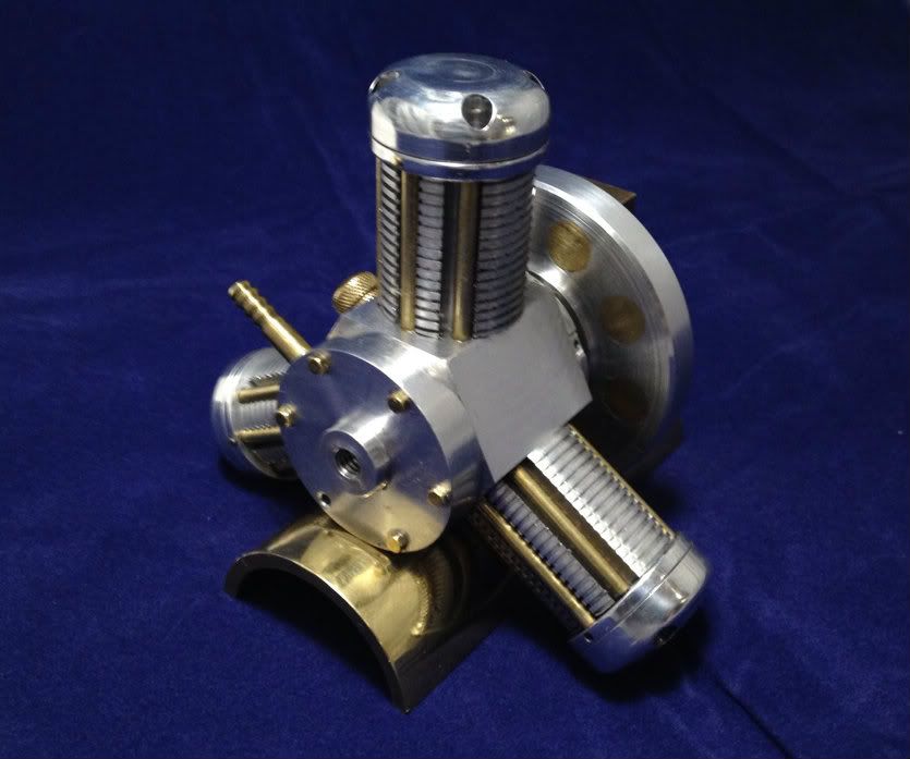
Family portrait.
OK. Enough making parts. Now to the section at least 2 of you have been waiting for.
If you've been following this thread, you know that it wouldn't run. Neither gaskets, nor higher pressure ("More pressure Scotty!" " I've given you all she'll do Captain,"), nor "running it in" on the lathe, nor Clover, nor gloom of night would make it run. Captain Jerry and Marcello kept sending great tips and things to try. One of these from Jerry was to drill more holes in the rotary valve so that ( with the valve housing removed) I could see exactly what was happening as far as piston position, air passage opening and closing, etc.
After determining that everything was doing what it should, I'm pretty sure that Jerry and I had the same though at the same time. The inside of the valve is the exhaust part and the outside of the valve is the intake control.
That meant that the valve action was reversed. The air was entering the cylinder at bottom dead center and exhausting just after top dead center.
Hmmm, that could prevent it from working.
So, for the 1,265th time I looked at the plans and saw this (hope this isn't a copyright violation, if it is the moderator will remove it and everyone can find the valve crank on the plans)
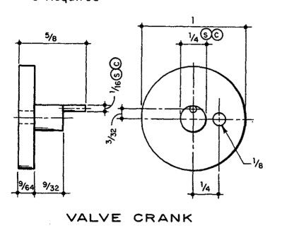
Maybe it's my inexperience at reading drawings or whatever, but I assumed that I was looking at the rear of the valve crank. Someone out there is saying, "Rear? Where did he learn to read plans? That's obviously the front of the valve crank. Jeez!!"
The only way I could see to reverse the intake and exhaust points was to drill another hole on the opposite side.
Did so and here's what happened. (The air passage for intake is the tiny hole just above the rotary valve)
A bit past Top Dead Center
A little further down
Botton Dead Center
The engine ( for the first time, felt like it wanted to run. It did 2/3 of a rotation and stopped at the same place each time. Something's binding and here it is. I know, it's not pretty but my hand filing skills are improving. Really.
This rod was not moving through its full range within the hub. Just a few strokes with a file and it's swinging the entire arc.
Now it turns better but still feel a tightness when rotating the flywheel by hand. Disassemble.
Reassemble feeling for binding at each step. No binding. Turns smoothly by hand. Put it back on the stand for yet another test. Now it's tight again????? Gotta be the stand. Arrrrrrgh. The two bottom cylinders are just touching the stand enough to push them out of line when the attaching screws are tightened. I just need to make recesses in the stand to eliminate contact with the cylinders. OK. Get to use the 1" end mill.
Reassemble for the 369th time and it's starting to run but not easily. I suspected air leakage and used the Precision Engine Leakage Tester (Dollar Store Bubble Wand Liquid). If anyone remembers Lawrence Welk, his bubbles had nothing on mine. The bubbles from the head leaks were all over the shop and quite pretty.
I cut paper gaskets for the heads. No leaks.
So, one misplaced hole in a crank, one sticky connecting rod, air leaks and one modification to the stand and I get this:
As frustrating as this was at times, I probably learned more from this engine than any I've built.
The troubleshooting was worth the price of admission. Without all of the help on this forum, this engine would have gone in a round tuit box under the bench. I'm glad I have a runner. My only regret is that, compared to the Grasshopper and the Open Column Twin with Poppet Valves, this one doesn't look very interesting when it's running. I'm going to put a propeller on it.
Best
Stan
The engine runs. It turns out that none of the changes to the engine (except one) were the culprit. All of the other pieces are to Elmer's dimensions. After the "customization" of the cylinders, the rest of the engine is in the "don't screw with these parts or it probably won't work" category. You'll have to wait for the the end of this post to find out the multiple causes that made this a non-runner and the fixes that made it a runner.
I'm not going to show stuff that you've seen and done hundreds (or thousands) of times, like "Hey, here's me facing a .250 rod on the lathe."
I'm going to hit things that, as a very beginning builder, I had to figure out a way to accomplish. Most of you can just page down over those things, but they may be helpful to novices like me. I've learned so much from Works in Progress that I really have a need to pass those on.
One piece of tooling that was extremely helpful was learning about the tiny live center that Bogs showed a few months back. I ordered it from ArcEurotrade and have used it a great deal. The connecting rods are a perfect example. Thanks, John.
Elmer wants the fixed connecting rod to be perfectly aligned with the central hole in the hub. (he actually said "Try to make the rod centerline pass through the hub centerline.") Try? What happens if you fail to do so can't be good, so I made a fixture. If the fixture looks suspiciously like a mis-made Grasshopper part .
I drilled three holes (not the big ones) to match the hub center, the pin for the rod and the wrist pin hole. With those in line, a little Loctite and done. Take that Elmer!
For my next trick, turning the tiny pin in the valve crank offset. (we'll be coming back to that valve crank later) Elmer sez "Do it in one piece" Not a prayer. More Loctite (remind me to check their stock price. It must go up when I build an engine). Then into a 5C collet and turn the spigot down until I can just see the pin. Precision at its best.
The vent plug. Pretty straightforward but I liked the way it ended up.
Turn down a piece of brass rod, thread and center drill, knurl and some lathe filing.
I made the flywheel from 6061 aluminum. Probably should have been brass for mass but I had none here. I later decided that additional mass at the outer edge would help. Drill, ream .375, press in brass plugs.
I then put the flywheel on a tapered mandrel and faced it.
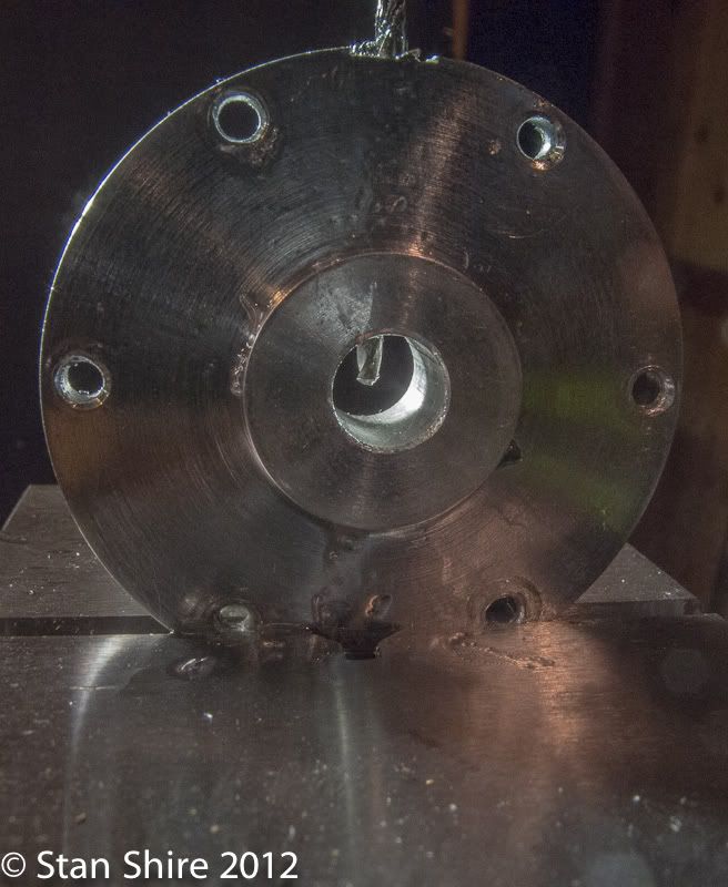
The crankcase cover has an oil passage but Elmer doesn't give an angle for drilling it.
I put the small sine vise in the milling vise (only so I wouldn't have to re-align the vise) and eyeballed the entrance and exit points for the drill by eye.
Amazingly, it came out perfectly!
After thinking about the base for days, I came up with a half-cylinder with the flywheel recessed.
I used the height gauge to scribe a line and then clamped the brass tube to keep it stable while it ran through the bandsaw.
Then clamped the cut piece in the vise and face milled the cut edges to level everything up. Have I told you how much I love that Glacern 45 degree face mill?
Then inverted the piece and milled the recessed for the crankcase, flywheel and rear bearing
And done. Drilling for mounting bolts ensued.
Family portrait.
OK. Enough making parts. Now to the section at least 2 of you have been waiting for.
If you've been following this thread, you know that it wouldn't run. Neither gaskets, nor higher pressure ("More pressure Scotty!" " I've given you all she'll do Captain,"), nor "running it in" on the lathe, nor Clover, nor gloom of night would make it run. Captain Jerry and Marcello kept sending great tips and things to try. One of these from Jerry was to drill more holes in the rotary valve so that ( with the valve housing removed) I could see exactly what was happening as far as piston position, air passage opening and closing, etc.
After determining that everything was doing what it should, I'm pretty sure that Jerry and I had the same though at the same time. The inside of the valve is the exhaust part and the outside of the valve is the intake control.
That meant that the valve action was reversed. The air was entering the cylinder at bottom dead center and exhausting just after top dead center.
Hmmm, that could prevent it from working.
So, for the 1,265th time I looked at the plans and saw this (hope this isn't a copyright violation, if it is the moderator will remove it and everyone can find the valve crank on the plans)
Maybe it's my inexperience at reading drawings or whatever, but I assumed that I was looking at the rear of the valve crank. Someone out there is saying, "Rear? Where did he learn to read plans? That's obviously the front of the valve crank. Jeez!!"
The only way I could see to reverse the intake and exhaust points was to drill another hole on the opposite side.
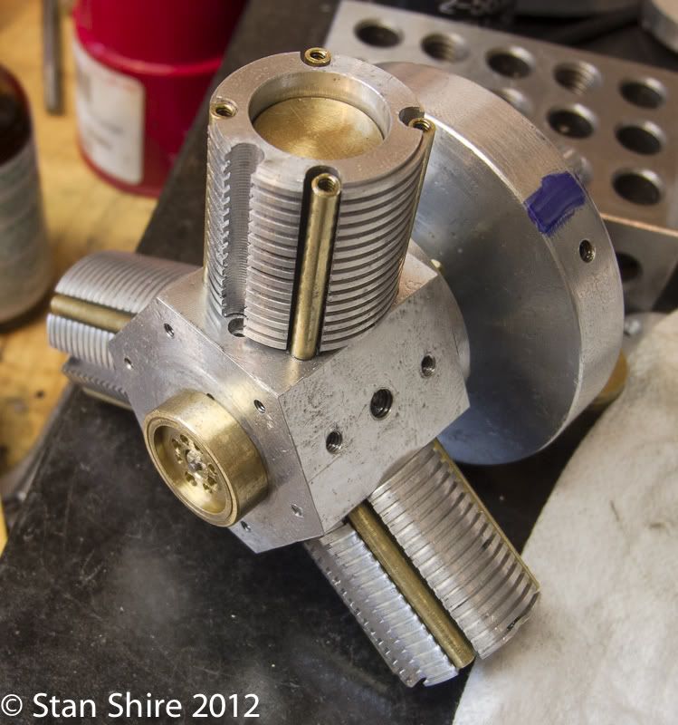
Did so and here's what happened. (The air passage for intake is the tiny hole just above the rotary valve)
A bit past Top Dead Center
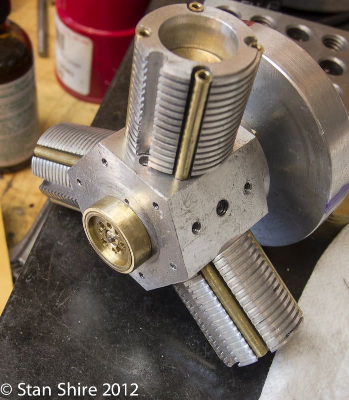
A little further down
Botton Dead Center
The engine ( for the first time, felt like it wanted to run. It did 2/3 of a rotation and stopped at the same place each time. Something's binding and here it is. I know, it's not pretty but my hand filing skills are improving. Really.
This rod was not moving through its full range within the hub. Just a few strokes with a file and it's swinging the entire arc.
Now it turns better but still feel a tightness when rotating the flywheel by hand. Disassemble.
Reassemble feeling for binding at each step. No binding. Turns smoothly by hand. Put it back on the stand for yet another test. Now it's tight again????? Gotta be the stand. Arrrrrrgh. The two bottom cylinders are just touching the stand enough to push them out of line when the attaching screws are tightened. I just need to make recesses in the stand to eliminate contact with the cylinders. OK. Get to use the 1" end mill.
Reassemble for the 369th time and it's starting to run but not easily. I suspected air leakage and used the Precision Engine Leakage Tester (Dollar Store Bubble Wand Liquid). If anyone remembers Lawrence Welk, his bubbles had nothing on mine. The bubbles from the head leaks were all over the shop and quite pretty.
I cut paper gaskets for the heads. No leaks.
So, one misplaced hole in a crank, one sticky connecting rod, air leaks and one modification to the stand and I get this:
As frustrating as this was at times, I probably learned more from this engine than any I've built.
The troubleshooting was worth the price of admission. Without all of the help on this forum, this engine would have gone in a round tuit box under the bench. I'm glad I have a runner. My only regret is that, compared to the Grasshopper and the Open Column Twin with Poppet Valves, this one doesn't look very interesting when it's running. I'm going to put a propeller on it.
Best
Stan
- Joined
- Aug 8, 2009
- Messages
- 930
- Reaction score
- 12
Congratulation Stan, a worthy model which will look fine on any shelf in the house (or workshop). I like the propeller idea too. Oh, and the heads themselves as well, they look like they should have been part of the original design.
Question: How did you eventually seal the air tube going up the sides of the cylinders? Is it friction fit top and bottom?
-dennis
Question: How did you eventually seal the air tube going up the sides of the cylinders? Is it friction fit top and bottom?
-dennis
Similar threads
- Replies
- 11
- Views
- 2K