


Mill tramming may be too mundane a topic for your graces, but what the heck, today it was mill tramming day and I think the first time I really got it OK.
Jerry G, webmentor to me and a bunch of younger and older sobs, suggested that all poor souls with a mill learn how to tram it properly... Everybody in class did it, but me. Now don't get me wrong, I'm not a slacker :-[ but life caught up, and a friend is visiting, and the car's sticker has expired, and a paper got accepted, and another is due, and a haircut is due even longer... so the mill mills happily, if untrammed, and me parts keep getting almost there but not quite there...
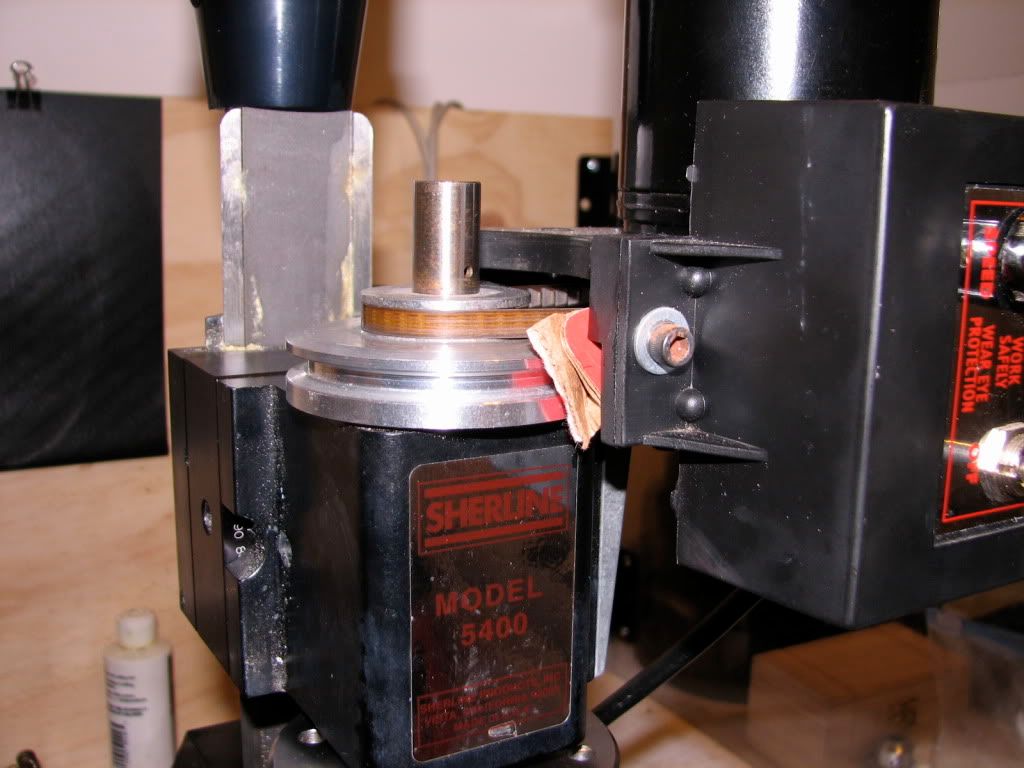
So today I decided to do what's most important and tram the little mill, a Sherline 5400. Here I follow what I understood from Jerry G, Dan D, and numerous other mates... I guess I'll blame them for what I did wrong (including misunderstanding what they wrote... I'm in me blaming mode tonight ).
First, I got me self a nice wheel bearing. Brought donuts to the guys who did the sticker renewal and asked for a scrap wheel bearing outer race. They were so nice and obliged... Gave me one with a huge scar inside the bearing's outer race... I shiver to think what happened to the balls...
I first filed some raised parts of the inner edge from the scarred side, and then went on using wet/dry paper. I moved the bearing in an "8" motion, on 600 grit paper after applying a mix of WD40 and some 3 in 1 oil... Gently...
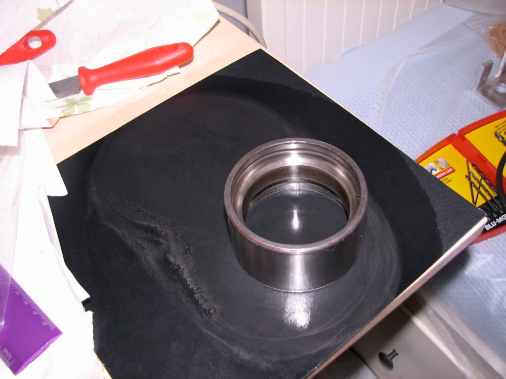
After doing that on both faces and seeing that I had nice, "fresh" surfaces I miked to make sure that the surfaces are parallel. At first they weren't -- cause I was not holding the mike carefully and perpendicular to the bearing...oh: after making sure that I knew how to measure, I found out that the faces were perfectly parallel. Of course.
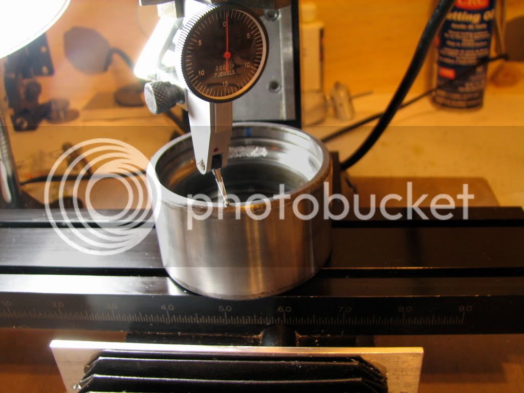
Then I mounted the 4 jaw chuck on the spindle and held my DTI so that it runs on the bearing race (diameter ~3").
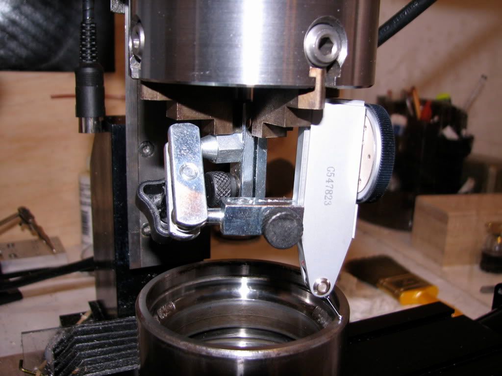
And then I started indicated what was widely held to be a decently trammed mill (that is by me and Anastasia). Well, setting 12 o clock to be the most distant part of the y axis and the reference height, 3 o clock was +0.002", 6 o clock was +0.003" and 9 o clock was 0.001" - all points lower than the reference. I repeated the measurements 4 times.
BTW -- I have marked the internal part of the bearing at 12, 3, 6 and 9 o clock using a blue sharpie and the rotary table...
... and I had locked the Z axis and put a carton wedge so that there is no play and the rotation is only clockwise (looking from above).
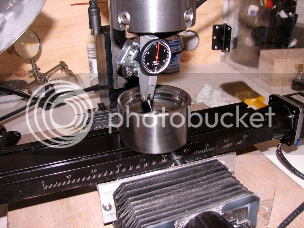
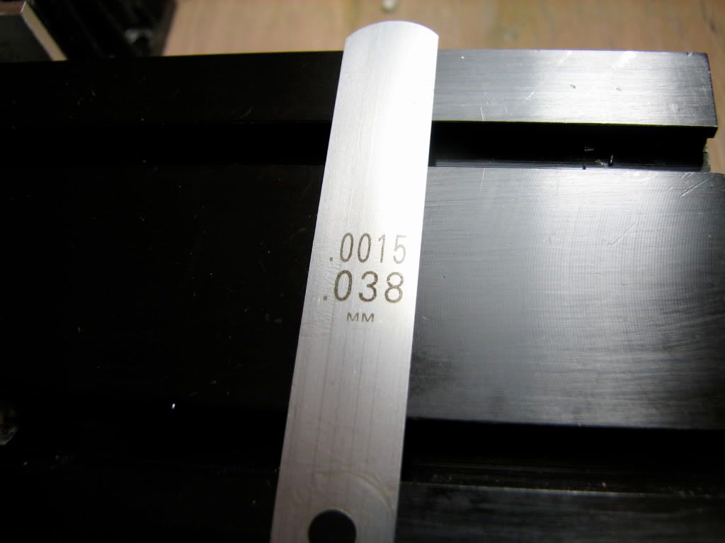
I first trammed the X axis so that 3 and 9 o clock read the same number: 0.0015". This is done by loosening the 4 screws that hold the Z column to its base... (no shown). So the problem remained the Y axis... The front part of the base needs to be lifted up a bit... So let's shim the base. After trying paper, coca cola cans and what not I went to the hardware store (JJ Rounds) where Bruce gave me stuff, including a feeler gage...
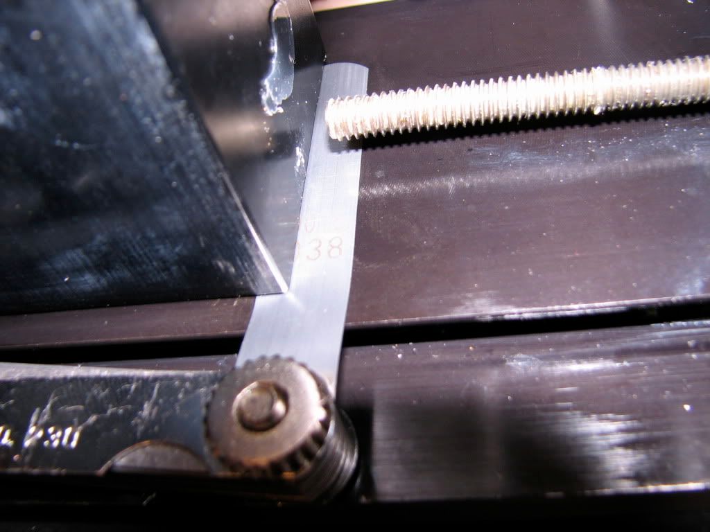
Trying different thicknesses, it seems that a shim of 0.0015" does the trick. So I cut two small pieces from the feeler gage :hDe:
Who cares.
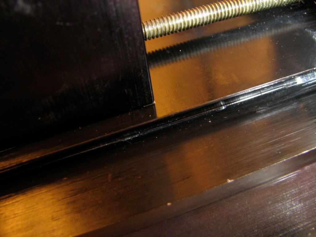
Here is the little piece under one side of the column base, in the front - barely visible. There's another one in the other side.
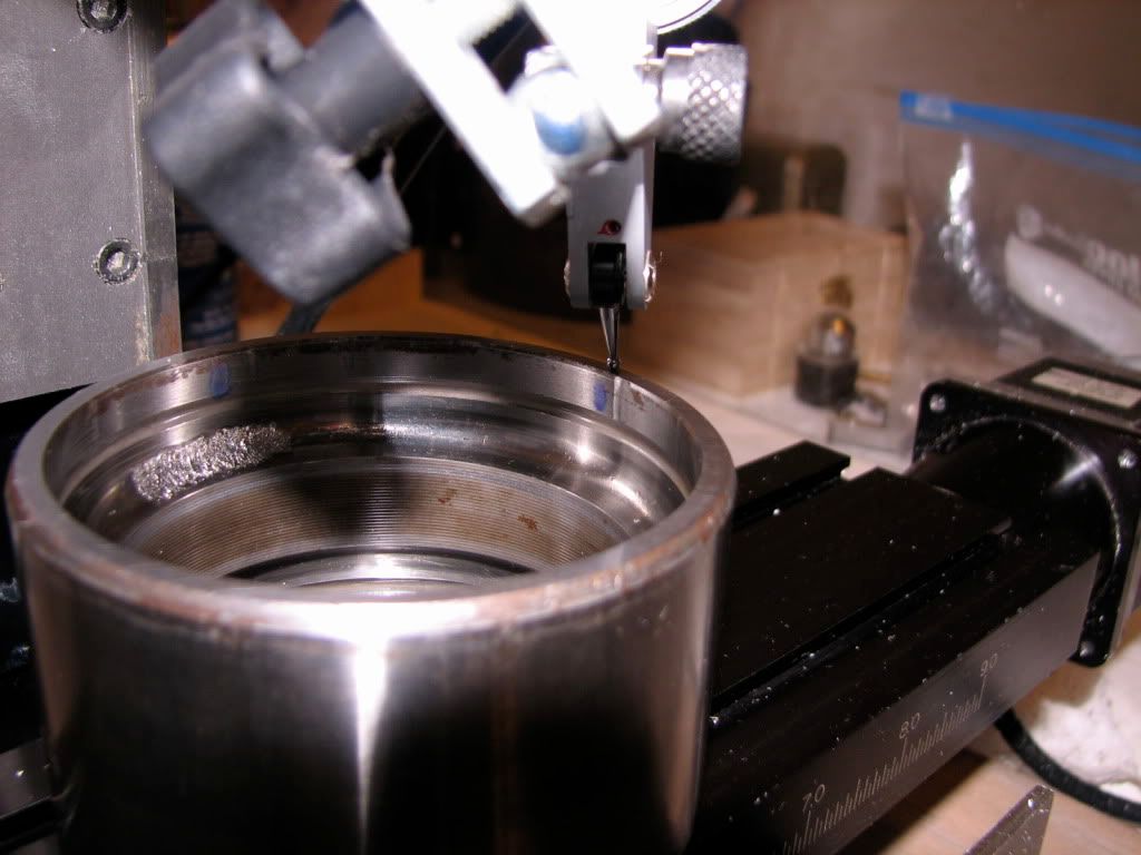
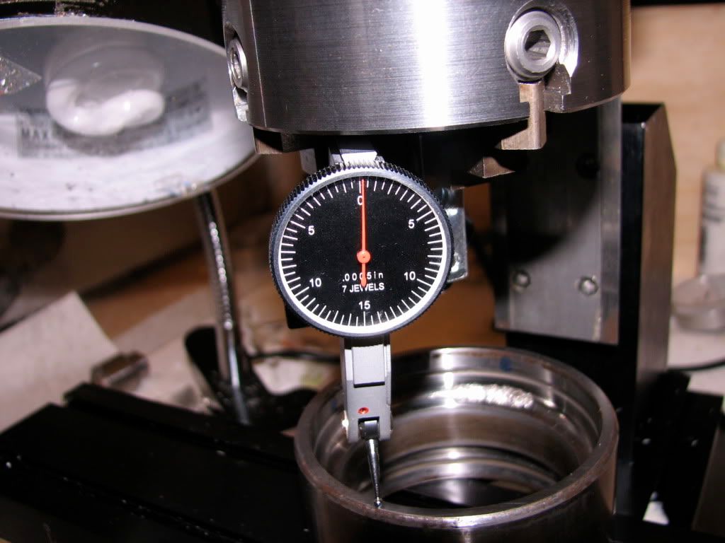
That did the trick. Here's 6 o clock (Sorry for the parallax error, I did not shoot the dial correctly) - 0.0000 -0.00025":
Here's 9 o clock. Again 0.0000 -0.00025".
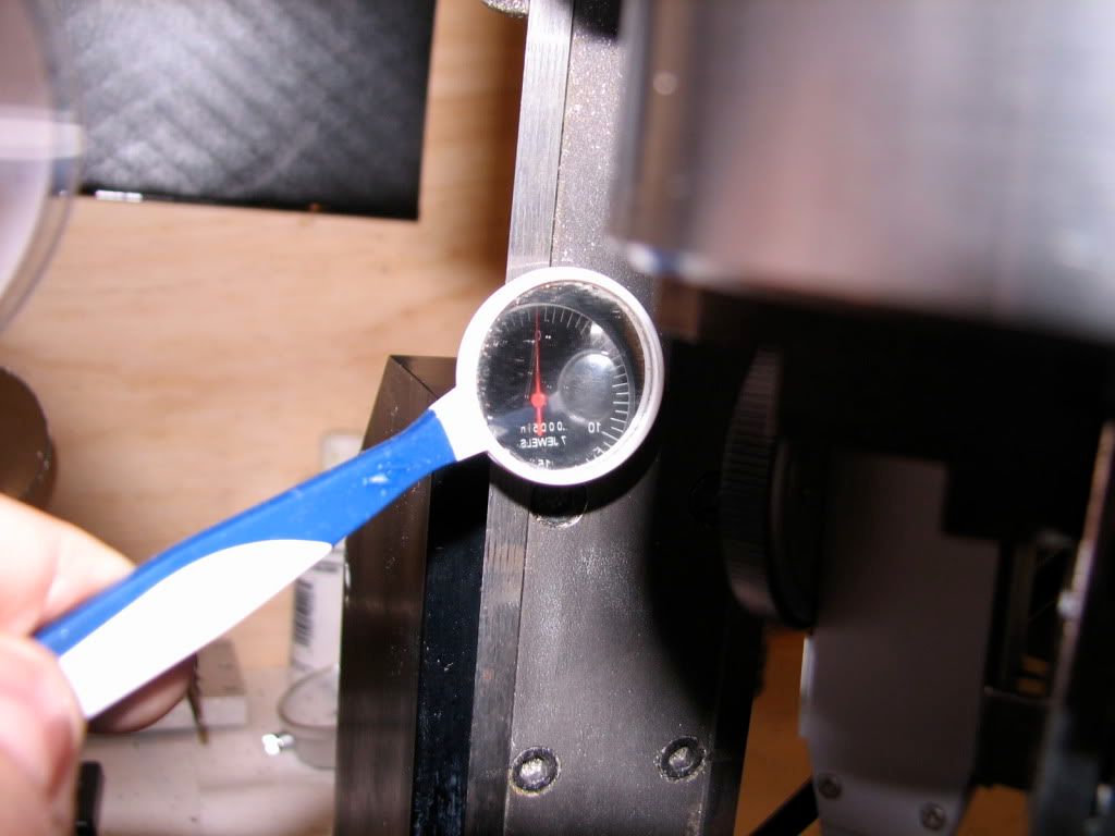
Here's 12 o clock- through the dental mirror I got at Walgreen's.... Again 0.0000 -0.00025".
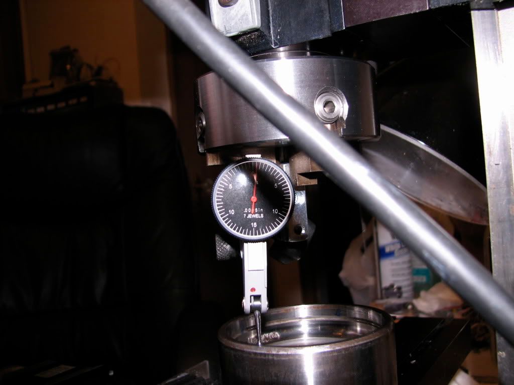
And finally, 3 o clock. A bit off -- 0.0005" - but who cares at this point... -- not me.
These measurements were repeated several times, and were stable within 0.00025". So I wore a smile on me face and went with my lovely wife for the beer I deserve.
If you see blunders let me know and I promise to put them in the booboos section
take care,
tom
Jerry G, webmentor to me and a bunch of younger and older sobs, suggested that all poor souls with a mill learn how to tram it properly... Everybody in class did it, but me. Now don't get me wrong, I'm not a slacker :-[ but life caught up, and a friend is visiting, and the car's sticker has expired, and a paper got accepted, and another is due, and a haircut is due even longer... so the mill mills happily, if untrammed, and me parts keep getting almost there but not quite there...
So today I decided to do what's most important and tram the little mill, a Sherline 5400. Here I follow what I understood from Jerry G, Dan D, and numerous other mates... I guess I'll blame them for what I did wrong
(including misunderstanding what they wrote... I'm in me blaming mode tonight ).First, I got me self a nice wheel bearing. Brought donuts to the guys who did the sticker renewal and asked for a scrap wheel bearing outer race. They were so nice and obliged... Gave me one with a huge scar inside the bearing's outer race... I shiver to think what happened to the balls...
I first filed some raised parts of the inner edge from the scarred side, and then went on using wet/dry paper. I moved the bearing in an "8" motion, on 600 grit paper after applying a mix of WD40 and some 3 in 1 oil... Gently...
After doing that on both faces and seeing that I had nice, "fresh" surfaces I miked to make sure that the surfaces are parallel. At first they weren't -- cause I was not holding the mike carefully and perpendicular to the bearing...
oh: after making sure that I knew how to measure, I found out that the faces were perfectly parallel. Of course. Then I mounted the 4 jaw chuck on the spindle and held my DTI so that it runs on the bearing race (diameter ~3").
And then I started indicated what was widely held to be a decently trammed mill (that is by me and Anastasia). Well, setting 12 o clock to be the most distant part of the y axis and the reference height, 3 o clock was +0.002", 6 o clock was +0.003" and 9 o clock was 0.001" - all points lower than the reference. I repeated the measurements 4 times.
BTW -- I have marked the internal part of the bearing at 12, 3, 6 and 9 o clock using a blue sharpie and the rotary table...
... and I had locked the Z axis and put a carton wedge so that there is no play and the rotation is only clockwise (looking from above).
I first trammed the X axis so that 3 and 9 o clock read the same number: 0.0015". This is done by loosening the 4 screws that hold the Z column to its base... (no shown). So the problem remained the Y axis... The front part of the base needs to be lifted up a bit... So let's shim the base. After trying paper, coca cola cans and what not I went to the hardware store (JJ Rounds) where Bruce gave me stuff, including a feeler gage...
Trying different thicknesses, it seems that a shim of 0.0015" does the trick. So I cut two small pieces from the feeler gage :hDe:
Who cares
. Here is the little piece under one side of the column base, in the front - barely visible. There's another one in the other side.
That did the trick. Here's 6 o clock (Sorry for the parallax error, I did not shoot the dial correctly) - 0.0000 -0.00025":
Here's 9 o clock. Again 0.0000 -0.00025".
Here's 12 o clock- through the dental mirror I got at Walgreen's.... Again 0.0000 -0.00025".
And finally, 3 o clock. A bit off -- 0.0005" - but who cares at this point... -- not me.
These measurements were repeated several times, and were stable within 0.00025". So I wore a smile on me face and went with my lovely wife for the beer I deserve.
If you see blunders let me know and I promise to put them in the booboos section
take care,
tom

