Toolpost Grinder - need help

Home Model Engine Machinist Forum

Help Support Home Model Engine Machinist Forum:

This site may earn a commission from merchant affiliate links, including eBay, Amazon, and others.

putputman

Senior Member
Joined
Nov 22, 2008
Messages
600
Reaction score
55
I am building a tool post grinder and am trying to make pulleys that will give me a particular speed on the grinding wheel. My target is 6600 rpm on the driven spindle. The motor spindle speed is about 8800. The motor specifies 7000 rpm at full load.

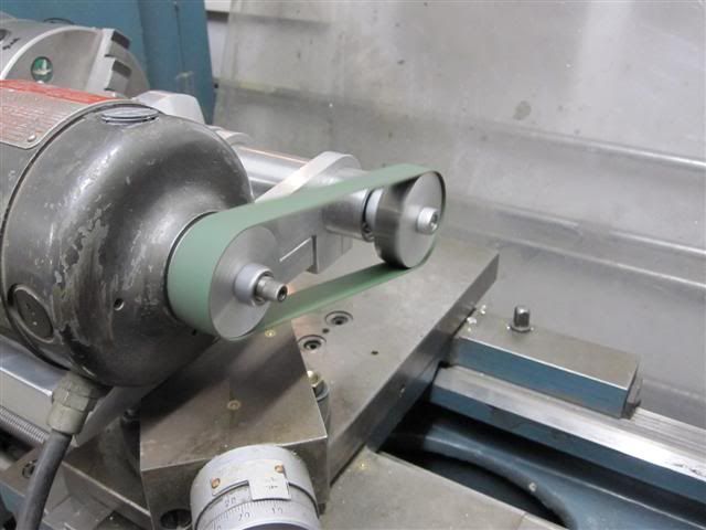
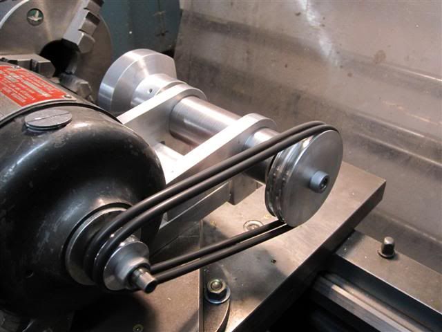
This is where I am at this point. I built a couple pulleys with o-ring grooves. I will use two 3/16 dia. o-rings for drivers. The pulley on the motor is 1" and the pulley on the spindle is 3" (2"wrong). These are the O.D. of the pulleys and there is are 3/16 dia grooves 094 into each pulley. I purchase o-rings that fit the grinder.

Toolpostgrinder.jpg


After mounting the unit on the lathe and powering it up I let it run for awhile to see if the bearing where adjusted OK and the motor run OK. It is a used motor. Everything seems OK to go.

Next I checked the rpm of the motor & spindle. Motor = 8800. Spindle = 3000.

This is where I need help. I want to achieve 6600 rpm on the spindle and be able to do it using the same o-rings that I have and the center distance is fixed between the motor and spindle.

What should the dia. of the driver and the driven pulleys be to accomplish this. It looks like it should be a simple algebra problem but both pulleys have to change in order to use the existing o-rings. Got my head swimming. ??? ???

Marv probably has a program already set up for this but I can't determine which one it is.
 
Seems you close enough for a practical test first, chuck up a piece of scrap and grind away, make sure the belts actually hold under load instead of slip. Then you will know if your center/center distance is good enough.
 
Marv probably has a program already set up for this but I can't determine which one it is.

You need to improve your reading comprehension fu, Arv.

At the very top of the software section of my webpage is listed BELT.ZIP with the following description:

While building a flat belt transmission system, I needed to calculate belt lengths and pulley sizes. The .zip file contains three programs. One to calculate belt length for an arbitrary arrangement of many pulleys, one to more quickly solve the same problem for two pulleys, and a third to calculate pulley size when the belt length is already set, as is the case with cone pulley speed changers.
 
The amount of belt you have on the pulleys is Pi*r so with 1" and a 2" diameter pulleys you currently have 3.142 x 1.5 = 4.71 inches of belt on your pulleys. This is what you have to share between the two pulleys.

To get your target speed you need 7000/6000rpm = 1.17:1 ratio

(4.71/2.17) x 1.17 = 2.54 inches of belt on the driven pulley which leaves 2.17 inches of belt on the driving pulley.

So your pulley diameters should be:

Driven: (2.54/3.142) x 2 = 1.61"
Driving: (2.17/3.142 x 2 = 1.38"

EDIT: just realised the target speed is 6600 but the maths still work if you change the numbers a bit. Best to err on the loose side and use an idler to tension the belt on the slack running side.
 
The speed relationship of the shafts is the same as the relationship of the pulley diameter.
 
be carefull with your rpms and make sure the wheels that you use will take your rpms, ihave seen small wheels on toolpost grinders get up to over speed and fly apart, with some bad injuries. be carefull jonesie
 
I personally think your are using the wrong type of belt. I think you will find with what you have, when you start to cut, you will get either bad surface finishes, or one will stretch and fly off.

You require something that has no stretch, like a toothed belt with associated toothed pullies, or like I have on mine, coned pullies with a woven flat belt. Maybe you could get away with a round leather belt or a specific round machine belting, we call it Redthane here.

Having two drive pullies and two rubber belts is asking for trouble, as if just one of the pullies is different in size, even by a minute amount than it's matching one, you will get one that creeps more than the other. I have the same problem with my lathe when I went to fit Redthane belts to it, one just kept getting thrown off and chewed up. I need to get all four pullies off my lathe and machine them to exact size. But then I need my lathe to machine them. Catch 22.

Normally, you do have a two pulley system, but one pair is used for the slower external grinding , and the other, when swapped over, runs the spindle much faster, for internal grinding.

As mentioned before, be very careful that you keep under the safe max speed of your wheels when doing your pulley size calculations, they are not something that can be played around with. Overspeed a wheel and you are playing with fire, or even worse.


Bogs
 
Thanks for all the input.
My 1st post had an error that I have corrected. The driven pulley was 3", not 2". The rpm's were based on those diameters.

Bogs, I agree that o-rings are not the best for drive belts, but they are readily available in my area. I do, by the way, have a 6 X 12 surface grinder that uses six 3/16 diameter o-rings driving a 7" diameter grinding wheel and I have never had any problems with it. Never had a o-ring break or jump off the pulleys. Maybe I am just lucky so far.

Another problem with my toolpost grinder is that I built it with a fixed center distance between the motor and spindle. I know now that was a mistake. That would make it almost impossible to find timing belts and pulleys to achieve to speeds I am looking for. I am stuck using o-rings or flat belts.

The speed I am looking for is 6600 rpm which is the speed recommended by Dumore for their 2-1/2" to 3" wheels.

I decided to use the 8800 rpm that I recorded on the motor while driving the 3" pulley and a 3" aluminum wheel to represent a grinding wheel. 8800/6600 = 1.33:1 ratio. Using that same ratio I came up with a 1.3" dia driver and a 1.725 driven pulley. Those two dia pulleys with the fixed center distance I have will allow me to use my existing o-rings.

Marv, I still could not find a program that would give me the pulley diameters for both pulleys by inputting the desired speed, center distance, and I.D of my o-rings. That is probably asking for too much with too little input. I did , however, use your belt.zip program and by trial and error, came up with a combination that will work out fine.

If this doesn't work out the way I hope, I may have to remount the motor and make it adjustable.
 
Arv,

I am not trying to teach you to suck eggs, but in the situation you are in, where you are calculating out pulley sizes, I would go for a single o-ring system, but dual pullies, one for internal and one external grinding.

You will have a bit of leeway in the stretch of the o-rings to take up any discrepancy in the calculations and machining, and one o-ring in the size you already have will certainly have enough strength to cope with both internal and external grinding (the cutting forces are minute) but none of the problems of having a pair of 'matched' belts or pullies. My skinny fabric flat belt is actually rather loose on my cone pullies, and can just be slipped off one onto t'other with no stretching required, that shows how little the cutting forces are.

If I remember rightly, my replacement motor, rather than running at 16K RPM of the original, actually runs at 13K or 14K RPM, and I turned up new cone pullies to account for the motor speed difference. But getting away from that, you will find that you will have to go the 'wrong way' for internal grinding and actually have a smaller pulley on the grinding spindle.

Internal mounted points are a lot more forgiving than external wheels with regards to running at the correct speed, having a very much larger spinning tolerance, some of the tiny ones can be used at well over 50K rpm. But in your situation, I personally would just reverse what pulley calculations you already have for your external wheel speed. That should give you around 11K RPM, a little slow, but acceptable for internal grinding with mounted points.

On Stews' build for his, he shows a cheapo method for making the holding collet chuck for mounted points.

http://madmodder.net/index.php?topic=1903.msg20864#msg20864

IMHO, it would be better if you went for the dual system, purely for the ease at which it can be done at the stage you are now at. It is just a matter of machining up a pair of matching pullies, but mounted opposite each other on the spindles. A two speed grinding spindle, instead of one.


Bogs
 
Judging by the pic in the first post, I think the o-ring belts could stand to be a little tighter.

Eric
 
Allthumbs is correct---those o-rings are way too loose. And o-rings will stretch to accomodate your pulley size. Don't let o-ring length be your limiting factor here---they are the cheapest and most accomodating part of your system.
 
Well Bogs, just as you predicted. When I got the pulleys made to give me the 6600 rpm I was looking for, the speed was so high the o-rings couldn't handle it. They created such a bow on the return side that they started to flutter and slip. I doubt that even shorter o-rings wouldn't solve the problem. I guess your never too old to learn how to suck eggs.

I had a 18-7/8 X ¾ flat belt that I used on my Economy engine and water pump. Using Marv's belt program and plugging in pulley diameters I came up with a combination that should give me the 6600 rpm. I made the pulleys and tested it out. I ended up with 8400 on the motor and 6450 on the spindle. Plenty close for me. There is no slippage or vibration so I think I got a winner. I ordered a couple grinding wheels that should be here in a few days. We'll see what kind of finish I get.

FlatBelt.jpg

 
My grinding wheels came in from MSC. I set up the 46 grit wheel, dressed it and ground a piece of soft CRS. I am happy with the finish, There were no chatter or vibration marks on it. The grinder performed well. I think if I were to grind a piece a hardened steel with the 80 grit wheel, I would come up with a beautiful finish.

Grindfinish.jpg


Grinder.jpg


My next part of this project will be to make a shaft for internal grinding. It is not too high on the TODO list so I'm not sure when this will happen.
 
Back
Top