Tiny Inline 4 Cylinder IC

Home Model Engine Machinist Forum

Help Support Home Model Engine Machinist Forum:

This site may earn a commission from merchant affiliate links, including eBay, Amazon, and others.
Wow, this project is getting even more amazing now! I've got my fingers crossed but am sure it'll be right!
:bow:

Nick
 
If I have learned anything from this web site it is that making a multi cylinder crankshaft if a very difficult process.

My intentions were to make a built up crankshaft, but my attempt at that failed horribly. After I pressed in the pins the whole thing was out of whack, to make matters worse, I accidently cut one of the crank journels off when removing the unwanted bits, so it was scrapped.

CIMG2000.jpg

CIMG2005.jpg


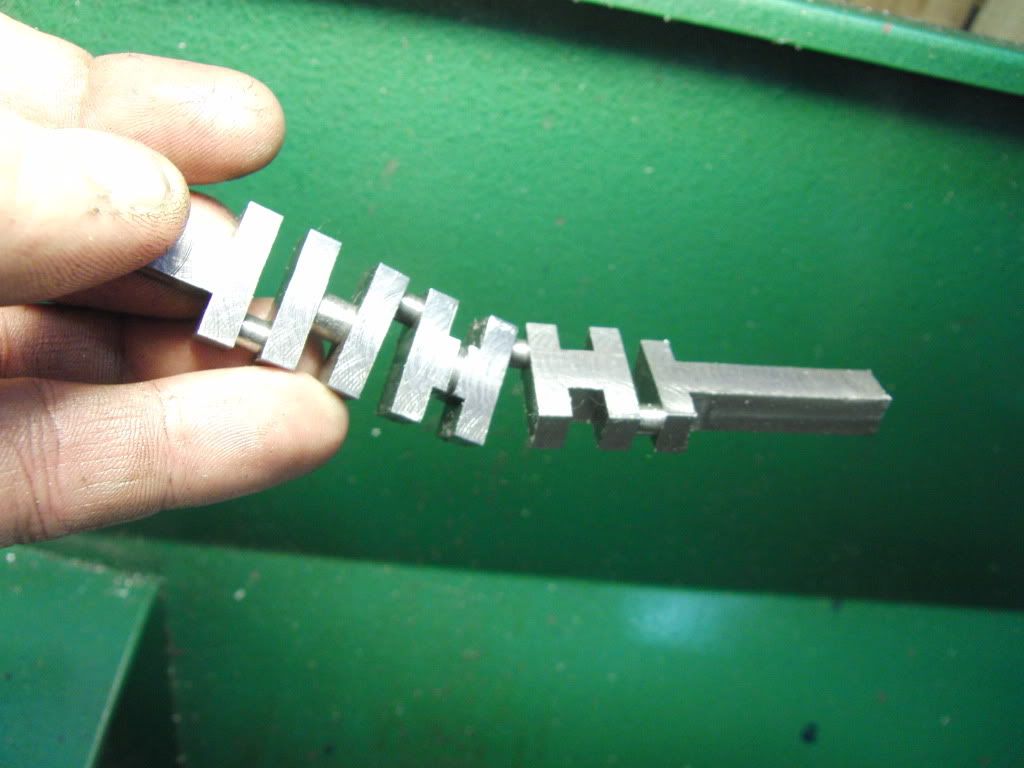
So I finally decided to make it in one piece. This is where the fun begins.

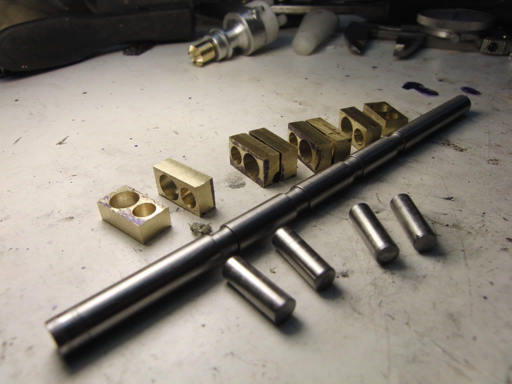
Since this is my first attempt I decided to use what I had on hand. Mystery Steel.

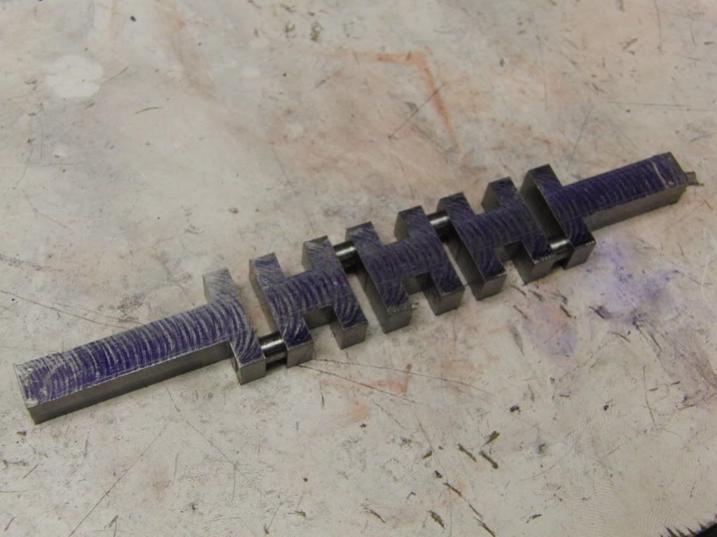
It was center drilled for the mains and throws.
CIMG2006.jpg


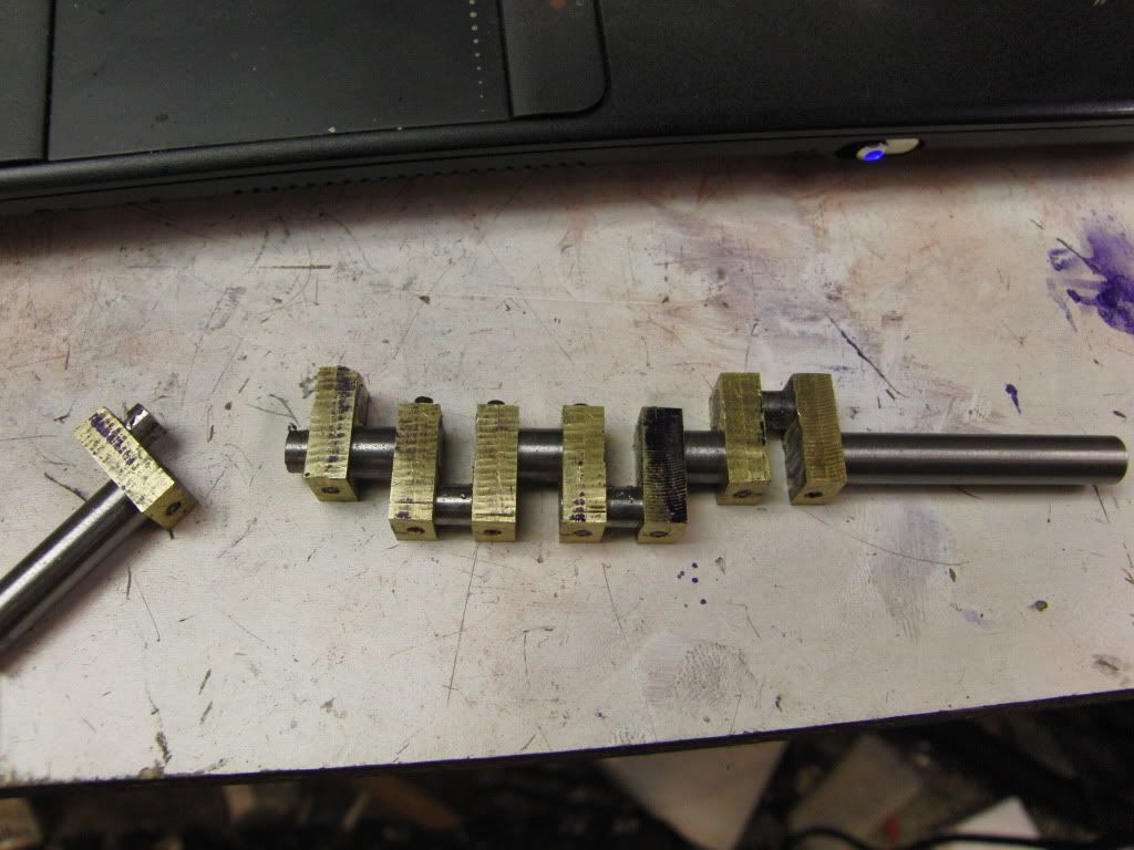
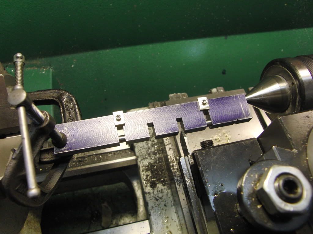
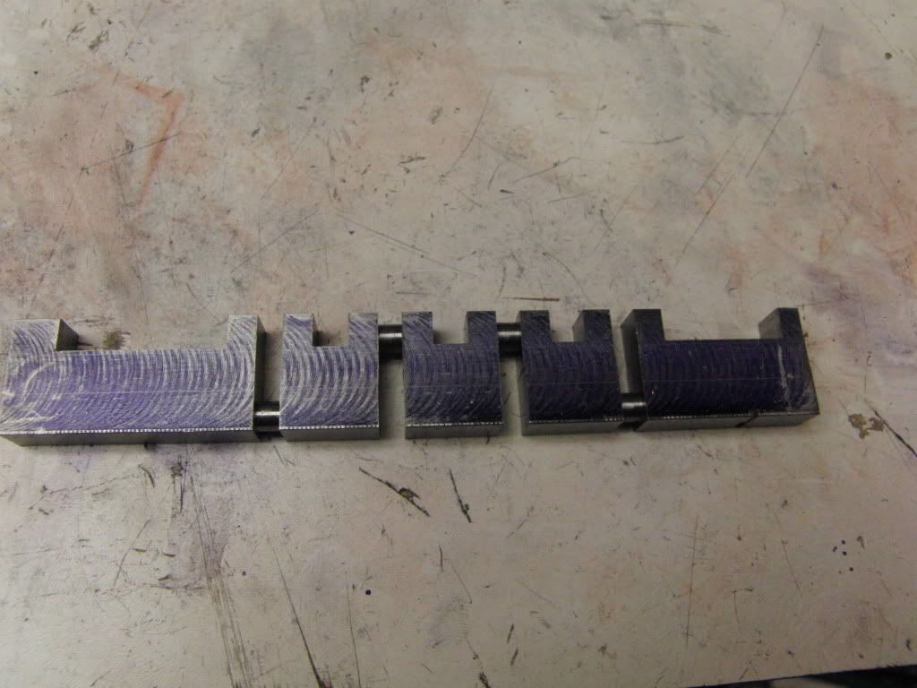
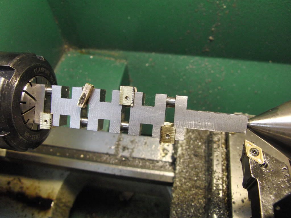
I am using the mill away then turn method.
CIMG2007.jpg


CIMG2011.jpg

CIMG2012.jpg


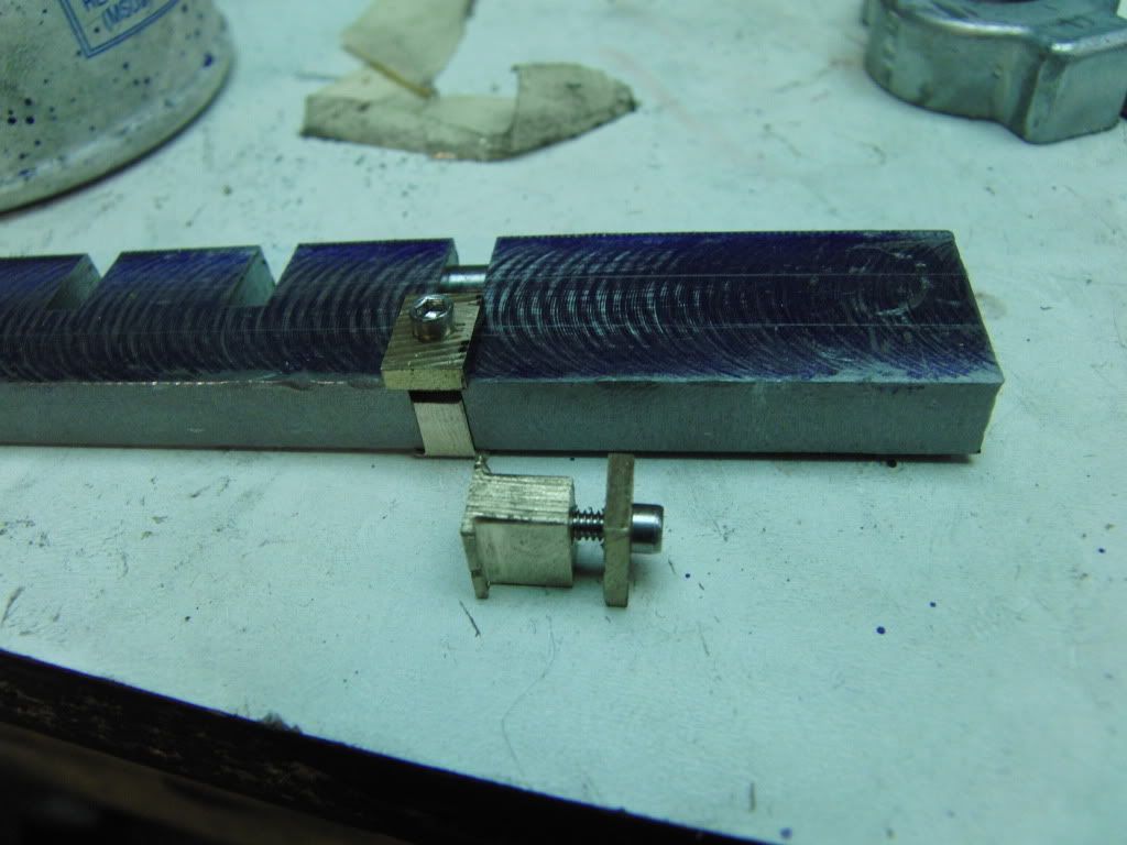
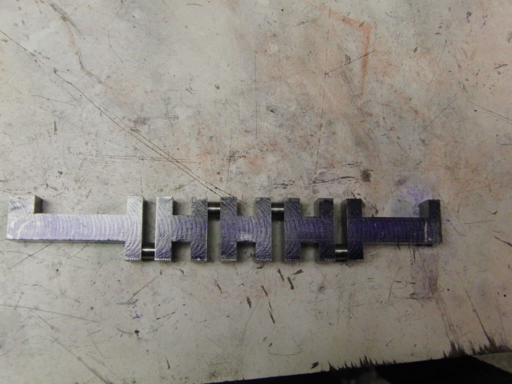
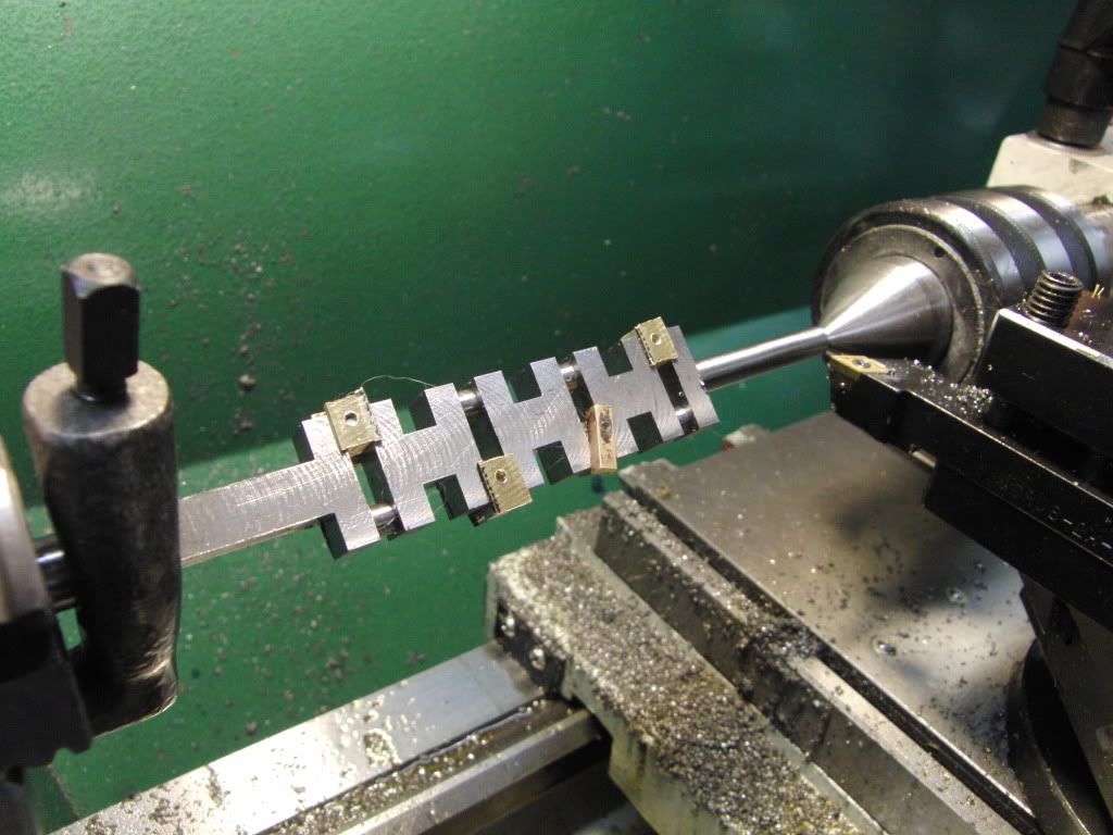
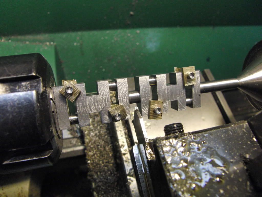
Here are the spacers which will stop the crank from crushing when clamped between centers.
CIMG2016.jpg


CIMG2017.jpg


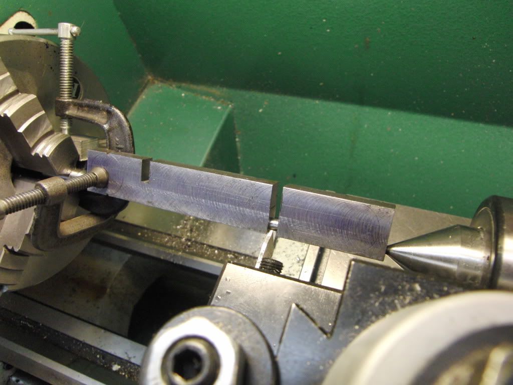
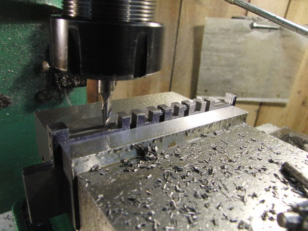
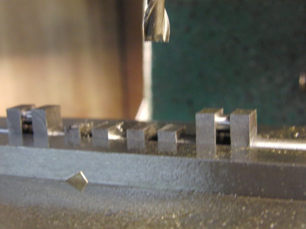
Back to the mill for the mains
CIMG2019.jpg


CIMG2024.jpg


CIMG2026.jpg


CIMG2027.jpg


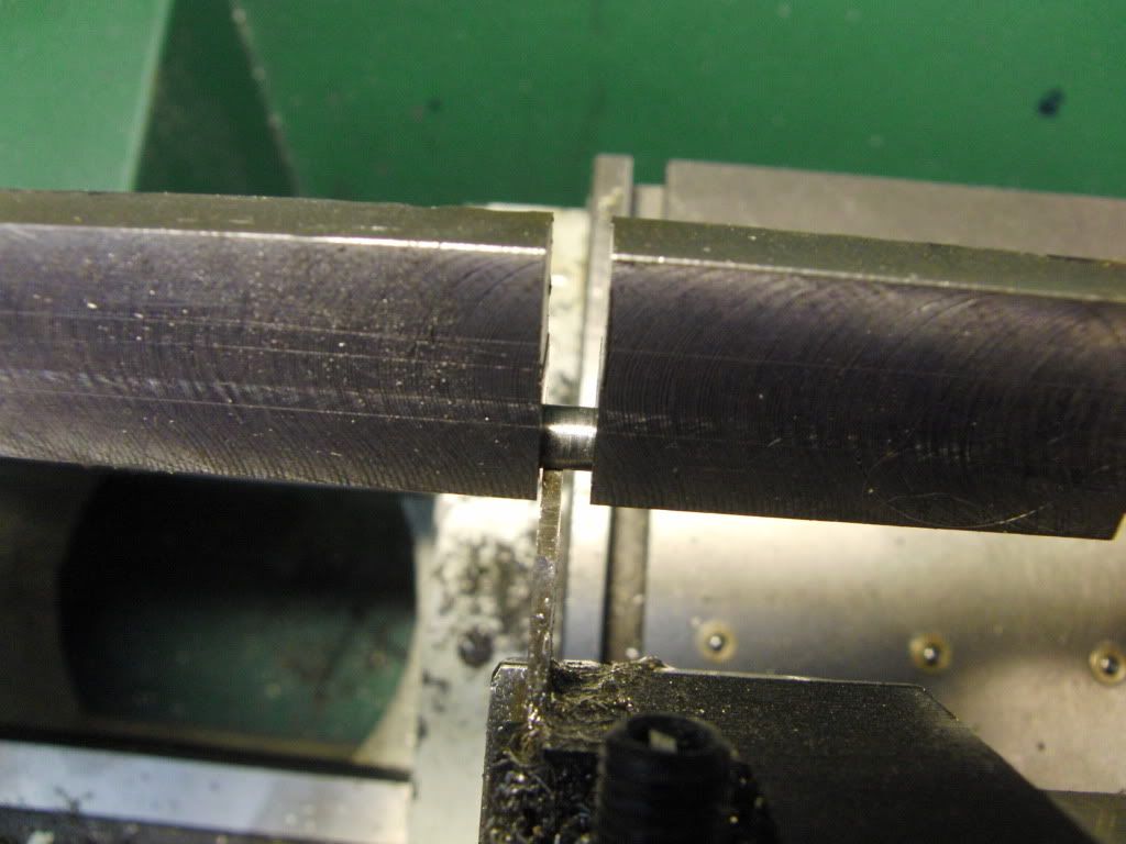
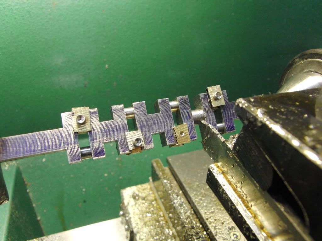
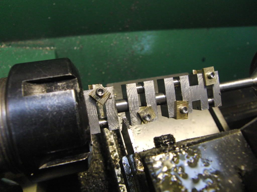
Cutting the first main.

CIMG2030.jpg


CIMG2030.jpg


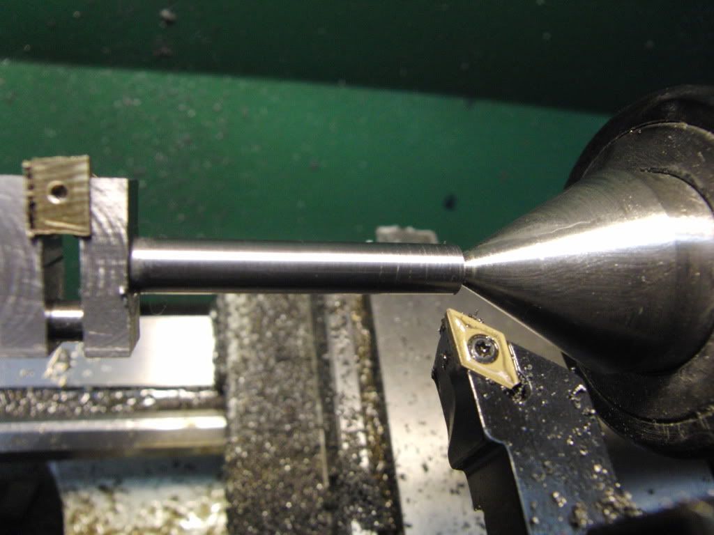
Up to this point everything was going OK, except for the chatter I was getting from the cut off bar, but I figured it was from the interrupted cuts.

Well, as I started to cut the second main journal a horrible noise was heard, the cut off bar caught up on the part and turned my crankshaft into a banana. I was't even hungry. I let out a quite @#$%, and said to myself, "Self, that wasn't to bad for your first try", and quietly shut the lights off and went upstairs to contemplate what I had done, aside from loosing 7 hours shop time.

CIMG2032.jpg

CIMG2031.jpg


I am thinking that a proper indexable cut off tool is in order, but I am not sure.

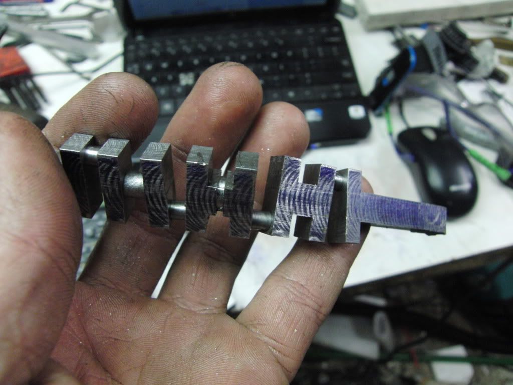
I tried to give the crank a little twist, and even with 3/16" journals it is incredibly stiff, and will not be bent back into shape, every throw is twisted and out of line.

I really liked making this part, even though I failed, it is not a failure.

Any suggestions on how I can change my setups, or the order of machining operations?

Kel
 
Kel, that was great photos and documentation and good method and machining until "it" happened. You weren't turning that with those C-clamps on the chuck end. Were you?

With the experience you have now, the next one will be a breeze. I hope. Good luck.

ironman (Ray)
 
Kel,
I have done a few and this is what worked the best for me.
First machine the throws as you did.

Then machine the shafts on each end to size. You can use a proper turning tool here so it is easier.

Then chuck one end with a minimum of overhang. I use a collet, but you can do it in a 4 jaw leaving just enough room to get an indicator in to adjust to run true.

Now cut the center main journal. It is the hardest one as it is the most flex.

Then cut the journal nearest the chuck.

Reverse the crank, indicate if using a chuck, and cut the last journal.

Gail in NM
 
Phil Duclos recommended milling the throws and journals round and to slightly oversize. He had them mounted between centers to do this. It would be the way I would go, and then do the final turning to size.

I would superglue blocks into the journals that your not machining...much like you have in the photo's

If you wave a propane torch at them, the glue will let go.

The end mill will be much less likely to grab during a cut than a parting tool, and the forces will be lower.

Then make a bifurcated turning tool...very thin. and finish turn the last .005" or so off the diameter.

That's what I'd do anyway.....Good luck to you!


Dave
 
Thanks Ray, Gail, and Dave.

Ray, I am in desperate need of a bigger lath dog. I will be making one BEFORE my next crankshaft, It went well, but thats not to say it wasn't sketchy, I had a full face shield on and stood to the side, just in case. I am glad you pointed that out.

Gail, Thanks for the advice, I will be using the collet method as you described, sound like a better choice.

Dave, I was thinking about something similar, perhaps using the R/T to get the journals oversize.

Kel
 
Kel,
That was a great job on the crank, discounting the outcome. Dave and Gail gave some good advice about turning the mains on the ends and chucking up as close as possible. Also the use of a bifurcated tool helps immensely.
I don't mean to hijack your thread but here is a link to my build of the Holt crank. Maybe this will give you a few more ideas.
http://bbs.homeshopmachinist.net/showthread.php?t=26132&highlight=holt+crankshaft
George
 
Congratulations Kel! Its kinda a rite of passage to have one pretzel hanging up on the wall 8) Sit back, have a beverage attack it again tomorrow.
 
Hi Kel. Don't let it bother you. It happens sooner or later to all of us, and in my case time and time again!

My last OOPS was a valve stem. I hooked the head with my cutter and pulled it clean out of a collet.

It looked like the business end of a well made cork screw!

Although you will probably want to make a new one, your crank dosen't look all that bad.

-MB
 
Round Two.....

I started over this morning with the crankshaft. All the procedures are the same until one point.

This pic shows the crankshaft main getting turned down on one end.
CIMG2033.jpg

CIMG2034.jpg


Next I turned it around and put it in a 1/4" collet, as per Gail's recommendation.

I made the other end round.
CIMG2036.jpg


Then I proceeded to cut the canter main journal, and WOW what a difference, there was very little chatter, and everything went swimmingly. Thanks Gail.

CIMG2037.jpg


CIMG2038.jpg


Then it was off to the mill to remove the excess material from the throws.
CIMG2040.jpg


And here is the finished part, somewhat.
CIMG2045.jpg


As with most things this seemed harder to think about than actually doing, it got a little hairy at times, but with patience it can be done. This is now my preferred method of making a crankshaft, maybe now I will try to make a single throw :big: :big:

One more pic with the inspection crew, they noticed a bit of a concetricity issue with one end of the crank, it seems to be off center, If I can't fix it, than it is yet another scrapped part. ???

CIMG2041.jpg


Kel
 
Looks real good! Ill bet it didnt take half the time the first one did.
Even factory crankshafts get "tweaked" for concentricity at times, if all your bearing clearances are fine, it might not be anything to sweat.
 
I question the collet method cuz if your collet isn't dead nuts your mains won't end up colinear. You won't know that though until you try to bed it in the bearings. Just for fun set the end mains in v-blocks then dial indicate the center main just to see how lucky you've been.
 
Nice job Kel! Only cranks I have ever done have been single throws I have yet to build a multi cylinder IC engine.
I know what your saying when you say you stood to one side I have done that a few time in the past. :big:
 
Great result and a good tutorial for anybody else doing it. I was well impressed when I did my tiny stirling - all be it a lot shorter than yours but it had 1/16" dia journels!

Nick
 
You have great patience KC and it paid off! A real challenge too doing a five main bearing shaft, wonderful to watch.
Stew
 
Thanks Everyone for your replies.

Unfortunately this crank is also destined for the scrap bin. I checked it in the block and it rocks back and forth between the three middle bearings, and the end mains are completely off center, I used an indicator and ther are between 5 and 20 thou out, so it is hopeless to fix.

I am thinking about getting rid of two or all three of the middle main bearings, and going with a different crank design where the crankshaft only has two journals and an angled web of sorts between throws, instead of a journal. I will get a drawing up soon to describe it better.

Kel
 
I may have just discovered something.

I indicated my collet chuck, and it showed .003" out. This had to be wrong, when I made it it had .0001" out. I also checked a 1/4" piece of drill rod and it was 5 thou out.

Hmmm, so I took off the chuck and noticed there was a bit of gunk in the threads and the register, so I meticulously cleaned the whole works, and reinstalled it. Checked it again, and BAM, Dead on, or at least much closer, with a drill rod it measured .0004" 1" away from the chuck. Much better.

I am still contemplating the new crank design without the middle journals.

Kel
 
aaaaaargh!! how maddening Kel, all your good work sabotaged by a faulty piece of tooling. So glad you found it though!!
Stew
 
Thats tough Kel, but you paid the price of that experience, doubt that problem will ever bite you again.

Before you scrap it, and while you have your measuring tools out, why not try to straighten it. Metal flows, much like putty, and in that it gives out its secrets. :) Start with a little nudge or tap with a hammer here and there, you will be surprised how easy it moves.
 
Back
Top