Tiny Inline 4 Cylinder IC

Home Model Engine Machinist Forum

Help Support Home Model Engine Machinist Forum:

This site may earn a commission from merchant affiliate links, including eBay, Amazon, and others.
It has been awhile since I posted in this thread. I am about 75% complete with the drawings and am continuing to work on them. I will be posting in this thread when the plans will be available.

After a month or so of computer work I got anxious to do some shop work. I seen a post from CaptainJerry on his mousepower dyno. I really liked the Idea and wanted to implement something for my TI4.

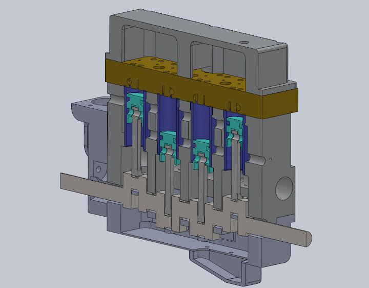
I decided to make it a separate device from the engine, then it could be used on multiple engines in the future, or to gauge changes in the engine, like cam duration and ignition timing and so forth.

Here is a video of the beginnings of my dyno. I picked up some force gauges of e-bay and this one reads in .01lb increments, with a total of 1lb. I have a prony brake on a 1 inch center, so the gauge reads directly in in/lbs from the driveshaft.

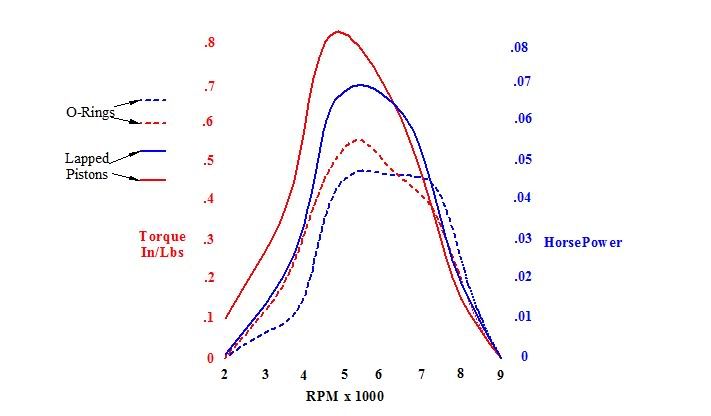
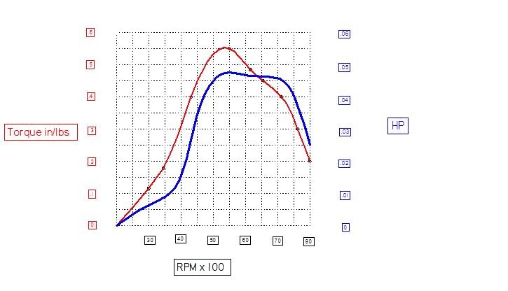
Doing the math and whatnot with RPM and torque I come up with a max reading of .05HP @ 6800 RPM, and .5 in/lbs of torque @ around 5000 rpm. I need to do some more testing to get a larger sample size for an average.

Let me know if I am doing anything wrong, or could do it better. My readings seem small, but than again 1/20th of a horse aint bad for something I made in my basement :big:


[ame]http://www.youtube.com/watch?v=jd3tXuJu1Gs[/ame]

Kel
 
Very cool. Power is all dependent on how well the engine can breath and at this cylinder size it's not easy to make a lot of power. I've been planning a dyno for a long time now, but am stuck with the control system.
 
Thanks Graig!

Here is a chart I made from an average of a few runs. I think I still need to refine my method a little bit, but I am getting a pretty consistent curve.

PowerData.jpg


Kel
 
I love the sound of that engine :)
Fantastic
Pete
 
Hey Guys,

It has been awhile since my last post again. I have been working on the plans most of the time, and I am now 99.5% complete. (Pending Review) Most of the engine has been modeled in 3D and checked for errors by Kevin "KustomKB" and Chuck "Kuhncw" , and I am confident I have a good set of plans. I am still searching through for typos, and any other un-satisfactory elements.

There is a total of 32 pages with 30 pages of detailed drawings with machining notes on a few of the pages. I have also included a write-up on making a camshaft the easy way. Once the blank is made, the lobes can be formed in about 20 minutes on the mill, with a rotary table.

The plans include drawings for the entire engine, water pump, radiator, fan and carburetor, with a list of references for materials, and notes on starting the engine. There are detailed views of some of the assemblies like the carb, distributor, and water pump.

I am confident the engine can be made on small machines like the X2 and Mini Lathe. I am not sure the capacities of the Sherline machines. The biggest limiting factor is the camshaft tunnel, which is a 3/8" hole, 3 1/2" Deep. This could probably be done on a lathe with a clever setup. The largest part is the block which can be made from a 1 3/4" square bar of aluminum 3 1/2" long.


The plans will be for sale in .pdf format for $40 US, and a hard copy will cost $55. I will accept PayPal as preferred payment method, as it is the easiest, but other arrangements can be made. The file, or hard copy will be sent once payment is received.

Send me a PM if you are interested.

Kel

 
Thanks Dale. That is indeed the formula I used.

Here is a re-post of my last post. It got buried in the bottom of the last page.

___________________________________________________________________
-----------------------------------------------------------------------------

I have been working on the plans most of the time, and I am now 99.5% complete. (Pending Review) Most of the engine has been modeled in 3D and checked for errors by Kevin "KustomKB" and Chuck "Kuhncw" , and I am confident I have a good set of plans. I am still searching through for typos, and any other un-satisfactory elements.

There is a total of 32 pages with 30 pages of detailed drawings with machining notes on a few of the pages. I have also included a write-up on making a camshaft the easy way. Once the blank is made, the lobes can be formed in about 20 minutes on the mill, with a rotary table.

The plans include drawings for the entire engine, water pump, radiator, fan and carburetor, with a list of references for materials, and notes on starting the engine. There are detailed views of some of the assemblies like the carb, distributor, and water pump.

I am confident the engine can be made on small machines like the X2 and Mini Lathe. I am not sure the capacities of the Sherline machines. The biggest limiting factor is the camshaft tunnel, which is a 3/8" hole, 3 1/2" Deep. This could probably be done on a lathe with a clever setup. The largest part is the block which can be made from a 1 3/4" square bar of aluminum 3 1/2" long.


The plans will be for sale in .pdf format for $40 US, and a hard copy will cost $55. I will accept PayPal as preferred payment method, as it is the easiest, but other arrangements can be made. The file, or hard copy will be sent once payment is received.

Send me a PM if you are interested.

Plans can also be purchased on E-bay, and directly off my website at www.BurleighMachine.com


Kel
 

I must say that Kelly has put together a beautiful set of drawings, the notes are very clear and easy to follow.

It has been a pleasure working from them. :bow:

I can't wait to hear my own engine running.


Kel Have you found someone to go over your plans yet I just had back surgery two weeks ago so I have a lot of time on my hands . Thanks Dale
 

Here is a video and a couple of pictures of some of the modeling I have done from Kelly's plans;

[ame]http://www.youtube.com/watch?v=Goz2RafdxrI[/ame] Please excuse the spinning distributor ;)

KK%252520tiny%252520in%252520line%2525204%252520x%252520section%2525201.JPG


1%252520angle%252520head.JPG


It has been a lot of fun and I can't wait to get started!


I strongly second what KustomKB said. Kelly's plans are a fine piece of work.
He's put in a lot of effort to make the drawings clear and easily understood. I recommend these drawings to anyone looking for a nice barstock, multicylinder engine project.

Kelly, thanks for the chance to help just a bit on your project. I enjoyed it a lot.

Regards,

Chuck Kuhn


Thanks for the kind words Kevin and Chuck! And thanks for uploading the 3D views Kevin, they look great!

Kel

 
I have been playing with new piston designs, mainly getting rid of the o-ring, and trying out rings or lapped pistons. My first attempt at rings was going good until I tried to start it, and there was virtually no compression.

I took the engine apart and checked the bores. I found them to be out of round by a few thou. So I decide to bore the engine out from .375" to .392". This increased the displacement of the entire engine from 3.62cc to 3.92cc.

I then decided to make lapped pistons and bores. As I did not have a lap, I decided to stick with the reamed hole, and using a 3/8" ball hone, got a smooth crosshatch pattern. I then made cast iron pistons to fit the bores with only .0002" of clearance.

This time I had success. The engine is much quicker to respond, and it starts much more easily.

So I had to hook it up to the dyno to see if there was any difference.

Before I was getting between .45 in lbs and .6 in lbs of torque and would die out quickly after putting max load on the engine.

After the piston mods I am now getting well into .8in lb - .9 in lb territory, and it will hold it at 6000 rpm for extended periods of time!!! This nearly doubled the torque!!!!!! I am having way to much fun now!

All this, and there is still a connecting rod bearing that had disintegrated resulting in quite a knock. I have been running it hard trying to throw parts so I can improve them, but it seems to be like my Toyota Corolla, it just wont quit. I even tried 20% nitro R/C fuel, and it still wont die!!

This is the first round of performance improvements. I would like to change the firing order so the intake runners are alternating between each power stroke.
This will require a new crankshaft to be made with alternating throws, and of course a new cam.

Til next time,

Kel
 
Kel,
The biggest improvement on my "Tiny" came when I went to lapped cast iron cylinder and piston. Ran cooler and started much easier.
Gail in NM
 
Well, you could make two intake manifolds that Y'd into two carburators. ::)
 
Did you notice any difference running the 20% nitro fuel?
John
 
Thanks Gail, your post on the Tiny was a great help in getting this engine running at where it is today.

Jeff, I had thought about that, but I think two carbs is twice as much trouble, but it would be cool though.

John, the engine needed a full turn or more on the needle to get it running, but once it ran, it screamed. It was much louder and the revving response was increased , but the max RPM was about the same, in fact with the new setup I can't quite get it to rev to 9000 anymore, but the loose connecting rod might be limiting it. I have not yet dyno'd it with nitro yet to get any numbers though.

I did run the engine again on the dyno to get some data. I had to reset the height of the gauge to get the prony brake level, and my numbers are actually a more modest .75 - .8 in/lbs max @ 4500 rpm but that is only momentary before killing but it can hold at .55 in/lbs @ 6200 rpm for extended periods of time. All the while that bearing-less connecting rod just won't give up! I was hoping the load would break it, but I am left disappointed ;D ;D:big:

Kel


Well I spent the last day collecting data on the Dyno. With adjustments to the ignition timing The TI4 is now holding the torque more effectively.

This is an average of a few runs, error on the high side.
I am absolutely confident that the engine has more torque with the lapped pistons. The data is considerably larger than before and the only thing that changed was the pistons. I did bore it out .015" over also, but I don't think that is enough to be the deciding factor in the increase of torque.

Here is the chart with the before and after data. Although this is a bit of a hairy test, it was at least the same from run to run, yielding different results.


DynoComparisonChart.jpg


Cant wait to do more mods now!!!

Kel

 
I have been running the engine on the Dyno through many tanks.

Through small adjustments of valve lash, timing, and fuel mixture the TI4 is running stronger than ever.

I am now seeing torque numbers in the .9 in/lb range and holding there at around 5500 - 6000 RPM. I am incredibly surprised at the strength and performance of this engine. I have been running it as hard as I can under load for extended periods of time and the thing just keeps going better than ever!

Math:
6000 RPM x .9 in/lb
63025 = (In/lb Factor for HP) (5252 if using ft/lbs)

= .085hp.

Right?

That is nearly double from the original engine!


What I am most excited about is there is plenty of room for improvement. Currently the valves in the head are hammered into their seats and beyond flush. So an open valve is only about half open and flush with the head surface. With a new head I could see even higher torque numbers. I might have to break out the 2lb gauge!!

Here is a video of the last dyno run.

[ame]http://www.youtube.com/watch?v=zeFsTuqT-14[/ame]


This is WAAAAAY to much Fun!!

Kel


kcmillin said:
Math:
6000 RPM x .9 in/lb
63025 = (In/lb Factor for HP) (5252 if using ft/lbs)

= .085hp.

Right?

I took today and Monday off as vacation days, I refuse to do math on my vacation. ;D

Your quick double check, is whatever formula you use, your HP and torque (in foot lbs) should be equal at 5250 rpm.

What I am most excited about is there is plenty of room for improvement. Currently the valves in the head are hammered into their seats and beyond flush. So an open valve is only about half open and flush with the head surface. With a new head I could see even higher torque numbers. I might have to break out the 2lb gauge!!

That is something I was afraid of with aluminum seats.
Halfway down on this page: http://www.homemodelenginemachinist.com/index.php?topic=11215.30
You can see where I used tool steel inserts for the valves. They seem to have worked good so far. If all goes well I will have my dyno up sometime this weekend.
 

Latest posts

Back
Top