Time for a new Horizontal Hit and Miss engine

Home Model Engine Machinist Forum

Help Support Home Model Engine Machinist Forum:

This site may earn a commission from merchant affiliate links, including eBay, Amazon, and others.
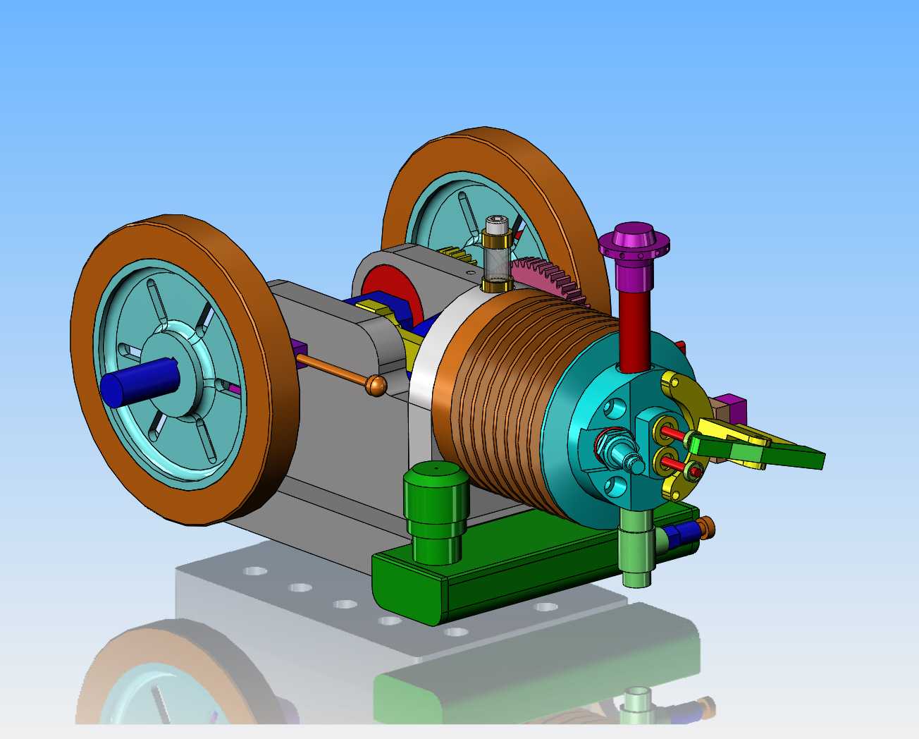
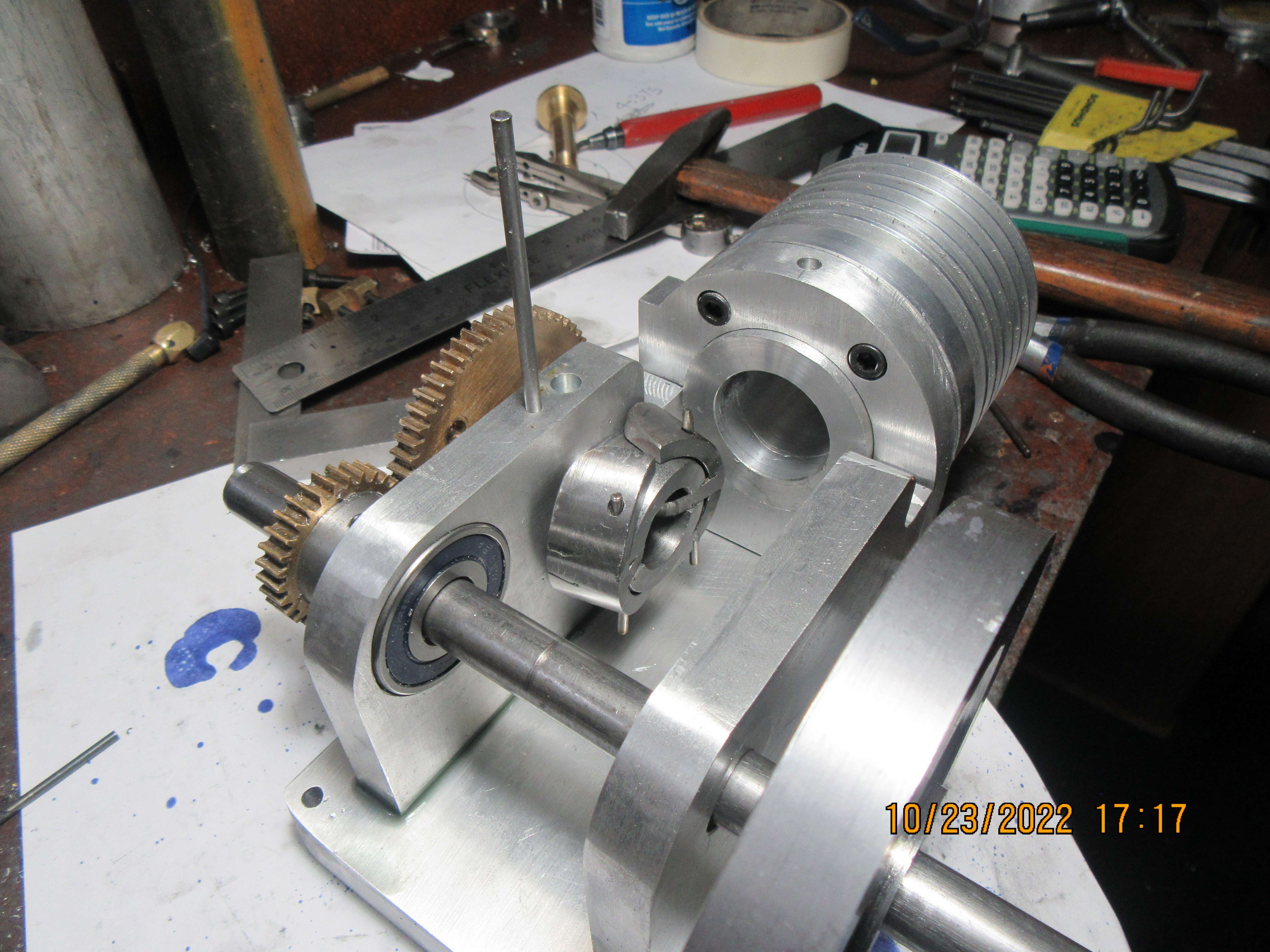
Okay---I like this. far end of gas tank is flush with far side of base, near side extends far enough beyond cylinder and base to allow room for the filler spout and cap. It also leaves the far end of the base clear so I can mount my ignition condenser there.
WlsDwD.jpg
 
I generally only use a double taper on the glow and diesel aero engines where the revs are much higher. Don't feel it makes a lot of difference on the hit and miss engine and lets face it you don't get any tapers on a Lunk just plumbed in with pipe which a lot of full size and models use. I think the only H&M that had a venturi was the ball hopper monitor
 
Okay--What to do, what to do.--I'm still waiting for that damned bandsaw blade to show up here. I did go across town to my metal supplier this morning and bought enough 3 1/2" aluminum to make two flywheel centers, enough 1 1/2" diameter 1144 stressproof to make a crankshaft, enough cast iron to make a cylinder liner, enough 3" diameter aluminum to make a cylinder head, and some 1 1/2" square tube to make a gas tank. I want something easy peasy to do this afternoon that doesn't require a bandsaw, so I'll make a couple of flywheel centers
lsaKZ0.jpg
 
First I machined the starter hub, which bolts to the face of one flywheel. (Setting on top of the flywheel material). Then I proceeded to cut the flywheel. Flywheels used to be easy, when I could just plunge in and cut the center relief and leave sharp edge corners. Now I cut that center relief with a 1/4" round nosed tool which leaves a beautiful 1/8" radius in the corners of the cut. It seems like a lot more work, but I'll get quicker as I do more flywheels. While I was cutting this flywheel, I realized that although I can cut half a flywheel into each end of the stock, I still have to use the bandsaw to separate the two flywheels from the main material. Ain't no way I'm going to try and cut 3 1/2" diameter aluminum with a parting off tool.
RYQDdb.jpg
 
I spent the rest of today finishing off the flywheel centers, finishing off the flywheel outer rims, and joining them together. The bandsaw played a big part in this, and my, but it's nice to have a new blade on it. The old blade was getting pretty dull, and then two weeks ago I finished it off by cutting a piece of 1" diameter bronze bar with it. Now there are two things I know not to cut on the bandsaw. #1---Don't cut drill rod, and #2 Don't cut bronze stock. The saw is quite happy cutting mild steel, both hot rolled and cold rolled, aluminum, and brass.
 
So how do you cut drill rod and bronze? Mostly I slow down the feed rate so that there is less load on the teeth. I have actually pulled back on the bandsaw frame to make less pressure. I have put new seals in my feed cylinder a couple of times. Also lube if possible.
 
Brian
There is a wax style lube that little machines shops in CA sells its comes in a round tube you just push out the product a tiny bitt an apply the moving blade its melts as it heat is formed from the friction you can feel difference. It doesn't leave quit a mess as other oil types.
Harvey
 
I also have a DoAll bandsaw and use it to cut all sorts of things. I have cut drill rod, shortened small grade 8 bolts, brass, bronze you name it and don't have any problems with blade life. One thing that comes to mind is what pitch blade Brian is using? In a home shop blade pitch is a real problem because we cut all sorts of things all different thickness. Something small like drill rod will dull a blade quick and even break teeth off if the blade is anything but a fine pitch (say 18-30 TPI). You can cut small stuff with the coarser pitch BUT its a real delicate balancing act, you have to feed it extremely gentle. It comes down to the old rule of at least 3 teeth engaged in the work thickness.

Bronze on the other hand is quite slippery and the blade does not like to "dig in" and cut, it likes to slip over the surface unless you put a lot of feed pressure. That slipping can generate a LOT of heat which is hard on a blade.

I don't know what Pitch blade Brian is using, I use something around 6-10 vari pitch for most everything and its always a compromise. Nobody wants to change a blade for cutting various pieces in a home shop so we just make one blade do it all which is hard on the blade. For steels I run the speed at around 200-225 feet per minute. (got that number talking with tech support from the blade company) I usually get a year or two out of a blade.

I will say that bi-metal vari-pitch blades last the longest by a huge margin. I never use any lube but should on larger pieces especially.
 
I use a bi-metal blade 0.025" x 1/2". It has a variable pitch, 6-10, and it costs me $62 including tax.. I do have the proper solid wax in the tubes to keep the blade slippery. Everyone has their own method of prolonging bandsaw blades--I use very little bronze or drill rod, and they cut okay on the lathe using a carbide cutting tool. I hope to get a lot of work out of that new blade today!!
 
Last edited:
I use a bi-metal blade 0.025" x 1/2". It has a variable pitch, 6-10, and it costs me $62 including tax.. I do have the proper solid wax in the tubes to keep the blade slippery. Everyone has their own method of prolonging bandsaw blades--I use very little brass or drill rod, and they cut okay on the lathe using a carbide cutting tool. I hope to get a lot of work out of that new blade today!!
Can't find any fault with the blade you use or how you use it. Its the same blade I use.
 
Last year I bought a great big vertical industrial Do-All bandsaw from a used machinery dealer in Toronto. I sold my old converted wood bandsaw to somebody who had a small hobby shop. I love my new/used bandsaw, but when the blade is dull you really know it.
 
Holy Cats, Batman!!! A few hours with a new bandsaw blade yields some nifty things. Everything is built "as per drawing".--Maybe that should be "As per Modell" I am very happy with the results. The bearings you see in the pictures will have their seals removed and all of the grease washed out of them. Oct -23-2022
cg9psl.jpg

moRaoK.jpg

hK7Jpp.jpg

Qefcno.jpg
 
The gears do mesh properly, and the governor fits where I wanted it to. The governor weights are shown in their "engaged" condition---They won't extend any farther into the con rod space. They miss the crankshaft and the con rod, but it's tight---very tight. So far everything is going as planned, but I may consider changing the bronze bushing that the camshaft runs in for a roller bearing. I will call Canadian Bearings tomorrow and see what sizes are available.
wX0hX3.jpg
 
Holy smokes! Brian, I am always amazed at how fast your models go from drawing board to workbench. This one is really cracking along! I'd still be fiddle-farting around with the cylinder, but you have this thing halfway finished already!
 
The gears do mesh properly, and the governor fits where I wanted it to. The governor weights are shown in their "engaged" condition---They won't extend any farther into the con rod space. They miss the crankshaft and the con rod, but it's tight---very tight. So far everything is going as planned, but I may consider changing the bronze bushing that the camshaft runs in for a roller bearing. I will call Canadian Bearings tomorrow and see what sizes are available.
wX0hX3.jpg
How is that governor put together--it looks like it would work well and far simpler than other governors.
 
Bob--to get these small hit and miss engines to "free-wheel" between firings, as the full size engines do, it is necessary to remove as much possible friction as you can. Removing the shields and the grease and lubricating the bearings with light lubricating oil is one of the steps towards very low friction.---Brian
 

Latest posts

Back
Top