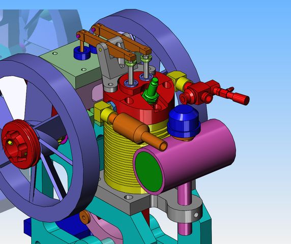
Thumper--a 1 3/8" bore i.c. engine

Home Model Engine Machinist Forum

Help Support Home Model Engine Machinist Forum:

This site may earn a commission from merchant affiliate links, including eBay, Amazon, and others.
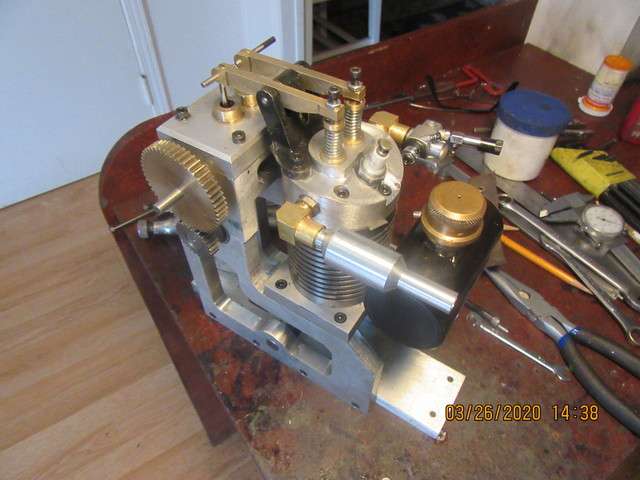
Today as I was making the brass elbows, I found myself wondering "what keeps the weight of the muffler or carburetor from making the elbows turn down, or "droop" when the engine heats up." There is no way that I can machine threads so that the elbows tighten up and "lock" in exactly the right position.----So--I went back to my 3D model for a closer look this evening. Hot Damn!!! I'm smarter than I thought. I had taken 1/4" thin hex nuts and retapped them for 3/8"-16 to use as lock nuts on the elbows to keep them positioned properly.
C7Vd2c.jpg
 
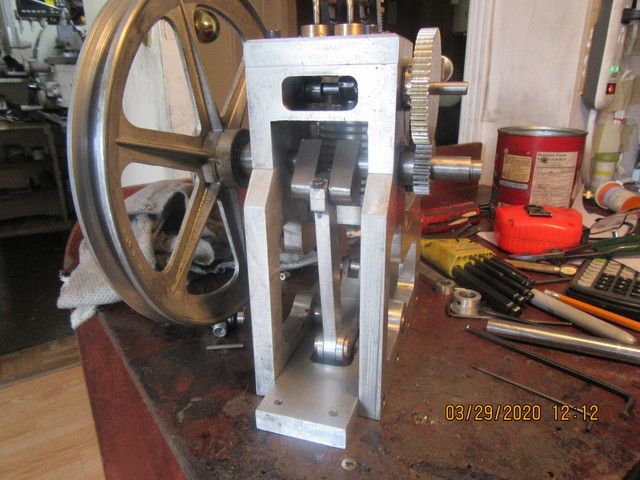
Today sees the engine completely assembled, except for crankshaft and flywheels. I have to make up some proper pivot pins with circlips for the rocker arms, but after I do that the crankshaft will be next. I am well pleased with things so far.---Brian
aaNnRb.jpg
 
Yesterday my rings came in from Debolt. They look good. They are exactly 0.094" thick. The grooves I cut in my piston with my 0.094" parting off tool are only 0.088" wide. Not sure how that happened, but it should be an easy fix. The rings have a staggered lap joint in them, which I didn't know would be there, but I'm sure they will probably work okay. Some horrible economics are involved with these rings. Debolt charges $8 each USA money for these rings. Change that to Canadian dollars, pay tax on it, then pay for shipping. Ends up costing me $56 Canadian. This morning I machined and installed an ignition cam. I went to make proper pivot shafts for the rocker arms, but I'm having an issue with concentricity. I checked my lathe head-shaft and chuck, and it has 0.003 TIR, same as it had when I bought it. The main chuck will only close down to 0.150", so I'm holding an extra smaller chuck in the main chuck. I'm getting crazy concentricity results and I'm not sure why, but will probably figure it out after posting this. As of today, I've been machining on this engine for 30 days straight. I may soon take a break and start setting up my TIG welder.
 
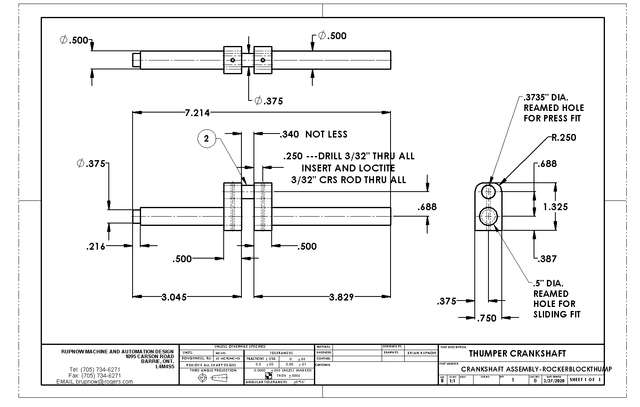
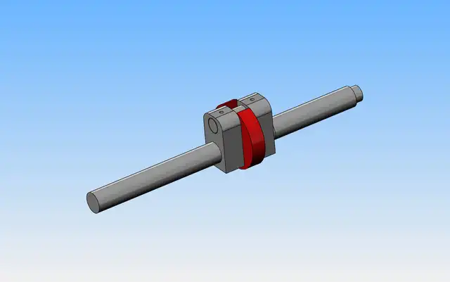
Every time I make a built up crankshaft, it goes a little differently. The only definite thing I have taken away from previous built up cranks, is to always make the main shaft out of one long piece and then mill out the area between the crank throws as an absolute last step. The other absolute "must" is to somehow attach the two throws together, either with indestructible glue or a dab of mig weld before drilling and reaming the holes. I have never, ever had any luck gluing parts together prior to machining. The glue always fails at some critical point right in the middle of machining. I have far more faith in mig weld. I do have the material on hand to make this, and I really don't want to be running around town to buy a piece of bar large enough to turn this from solid.
SSNfzc.jpg
 
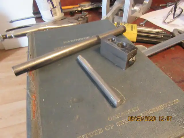
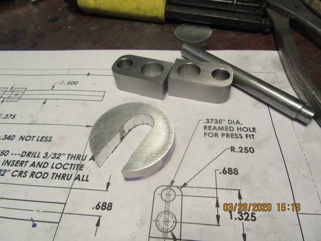
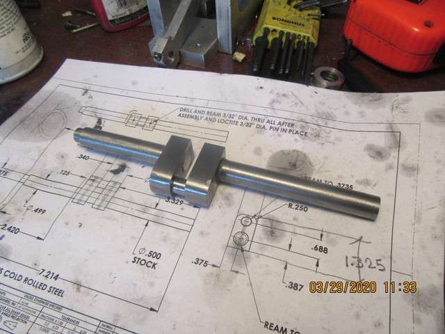
Okay Guys, hang on tight--Here we go. The main crankshaft body is being made from 1/2" cold rolled steel, which comes in at nominally about 0.001" undersize. It is cut to finished length in the picture. The 3/8" cold rolled steel also comes in at about 0.001" undersize and is not yet cut to finished length. The two pieces of 3/4" x 1/2" cold rolled flatbar have been mig welded together at each end, and then both bored and reamed to 0.0015" undersize, on the correct centers. The pieces of bar are a bit too long at each end right now---that is to allow cutting away the welded ends and finishing them to the correct length. These pieces of flatbar were not held in the milling vice for drilling and reaming, as I never really trust my vice to hold things perfectly square and not canted a bit. They were held to the mill bed with toe clamps and a piece of 1/2" sacrificial aluminum under them for the drilling and reaming operation. After I eat some lunch I will show you what comes next.
ysPHBP.jpg
 
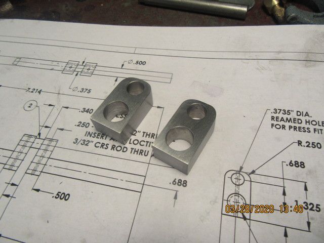
The two pieces of flatbar have been trimmed to length, by trimming and finishing one end while the other end was still welded together. then the second welded end was removed, being very careful to keep both pieces identical. They were then match marked so I could keep the inward facing sides together. Then they were taken out to my large belt sander to have the corners rounded as required. That corner rounding is a clearance requirement so the crankshaft doesn't hit the underside of the cam box when it rotates. Now I'm off for my "Fat mans walk", will post more when I come back.---Brian
oDT4nB.jpg
 
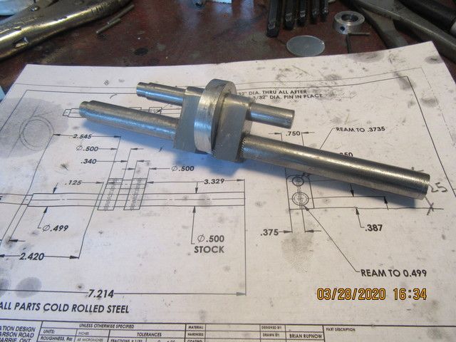
Things never go quite as I had planned, but they go, nontheless. When I went to assemble all of my parts, the 1/2" dia. shaft was nowhere near as hard a press into the cheek plates as I had hoped for. What to do, what to do. I couldn't make the hole in the plates any smaller, but I could make the diameter of the shaft a little larger. I set the shaft up in my lathe and knurled the area where the cheek plates set. This "grew" the shaft, from 0.499 up to 0.509" diameter. I don't have any kind of press except for a 3 ton manual arbor press and my bench-top vice. I coated the knurled area with 638 Loctite, and applied lots of brute force via my heavy hammer and things assembled just fine. Mushroomed the shaft end a little, but that cleaned up in the lathe. Right now I am not seeing any run-out in the assembled shaft, but the true story will come out tomorrow when I cut the 1/2" shaft away between the cheek plates. If it works, I'm golden. If it doesn't work, I'm out two or three hours of work. I'm going to drill the cheek plates and shafts now for the 0.094" pins, insert them, and let everything set up over night. I'll let you know the results in the morning.
wgPa1Y.jpg
 
Well sir!!!--I am very pleased with this. Crankshaft all cleaned up, and with one end in the lathe chuck, the other end registers a 0.003" total indicated run-out. That is equal to any of the one piece crankshafts that I have machined from solid. Crankshaft fits where it is supposed to go, and goes round and round. Oh Happy day!!!
bTCG3I.jpg

Jxg2Cu.jpg
 
This morning I test fitted the rings into the cylinder. The rings have a stepped gap, however when I had a ring pressed into the cylinder and held it up to a bright light, there was still clearance for the ring gap to close a little bit more if it expands with heat. I was satisfied with the fit of both rings. I set my piston up in the lathe 3 jaw chuck and very carefully opened up the 0.086" wide gap to about 0.095" to accept the 0.094 thick rings. Any time I cut a groove in aluminum, it raises a shoulder on each side of the groove. Not much of a shoulder, but enough to keep an already tight fitting piston from sliding into the cylinder. Knowing that, and knowing that a few people were alarmed at the thought of a tight fitting aluminum piston in a cast iron cylinder, I walked a piece of 220 grit garnet paper back and forth on the piston to knock down the shoulders and take about 0.0005" off the overall piston diameter. the rings went onto the pistons with no problem. I had the cylinder off the engine, so set it up in my 3 jaw and machined a 15 degree "lead" taper into the bottom to aid in installing the rings. everything went together fine. In about 15 minutes I'm going to make a head gasket and install it, and then the engine will be finished except for the flywheels.
 
The engine is finished---except for flywheels. There may a significant time span before I get the flywheels finished. I am now turning my attention to the flywheels, which will very probably be fabricated with my new TIG welder. Thank you, to those who have followed this thread, which was started 32 days ago.
 
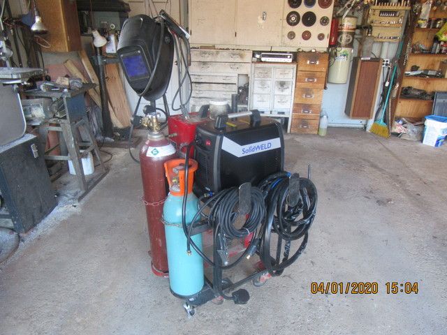
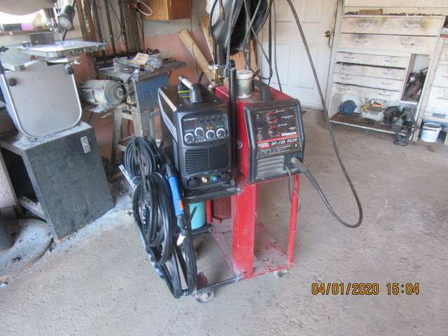
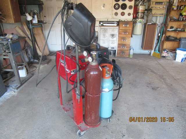
And this is how I spent the last two days. My welding cart which previously held only the mig has been widened about 9" and now holds both the mig and the tig. I hardly ever get to actually fabricate things any more, so I enjoyed doing it.
CwshXN.jpg

vvfM1q.jpg

7HuQoU.jpg
 
Brian,

Good job on your cart. I also don't get to do much fabrication anymore, so enjoy it when I can.

Thank You for posting, as always.

--ShopShoe
 
TIG and MIG?
I bought a TIG welder a couple of years ago. After a little practise with TIG, I sold my MIG welder.
The only thing I could think of where the MIG would be better was car bodies and I have no intention of doing any more of that.
 
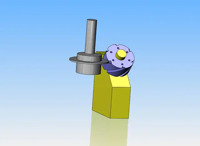
I woke up this morning thinking about how to fixture the hubs of the flywheels to cut the 45 degree slots in them. Sometimes if I model what I am thinking about, it helps to clarify things. It looks to me that if I make the yellow fixture, I can hold it in my vice and just crank the mill table back and forth in the X axis to cut the slots. I will have to drill a set of holes in the face of the hubs to register them on the yellow fixture so that they don't move while being cut.
8y7BmK.jpg
 
Last edited:
I have never used MIG, other than briefly in a class some years ago. But I do continue to use SMAW (stick) welding, alongside the TIG. I definitely get prettier results and more control with the TIG, but when working with larger cross-sections, the speed and quantity of weld available with SMAW, as well as the low cost of consumables, is nice to have. I wonder if the same might be true of having MIG alongside the TIG?
 
I like your method for spacing during the crankshaft pressing Brian. Knurling come in handy when stock doesn’t fit for crap!

Many, many moons ago, when I was a young flat track racer, the Harley KR I was riding developed excessive piston slap while out of town. We knurled the piston skirts by sandwiching them between two coarse files in a vise, gave it the tiniest bit of a squeeze, and then alternated tapping on the opposing files (causing the piston to rotate) until the entire skirt raised up a rough couple thou. knurl. Got me through the race!

John W
 
so those 45 slots, are those going to be to create cooling fins or fan blades built into the flywheels? if so how will you cut the internal slots on the inside of the outer flywheel ring?
 
Back
Top