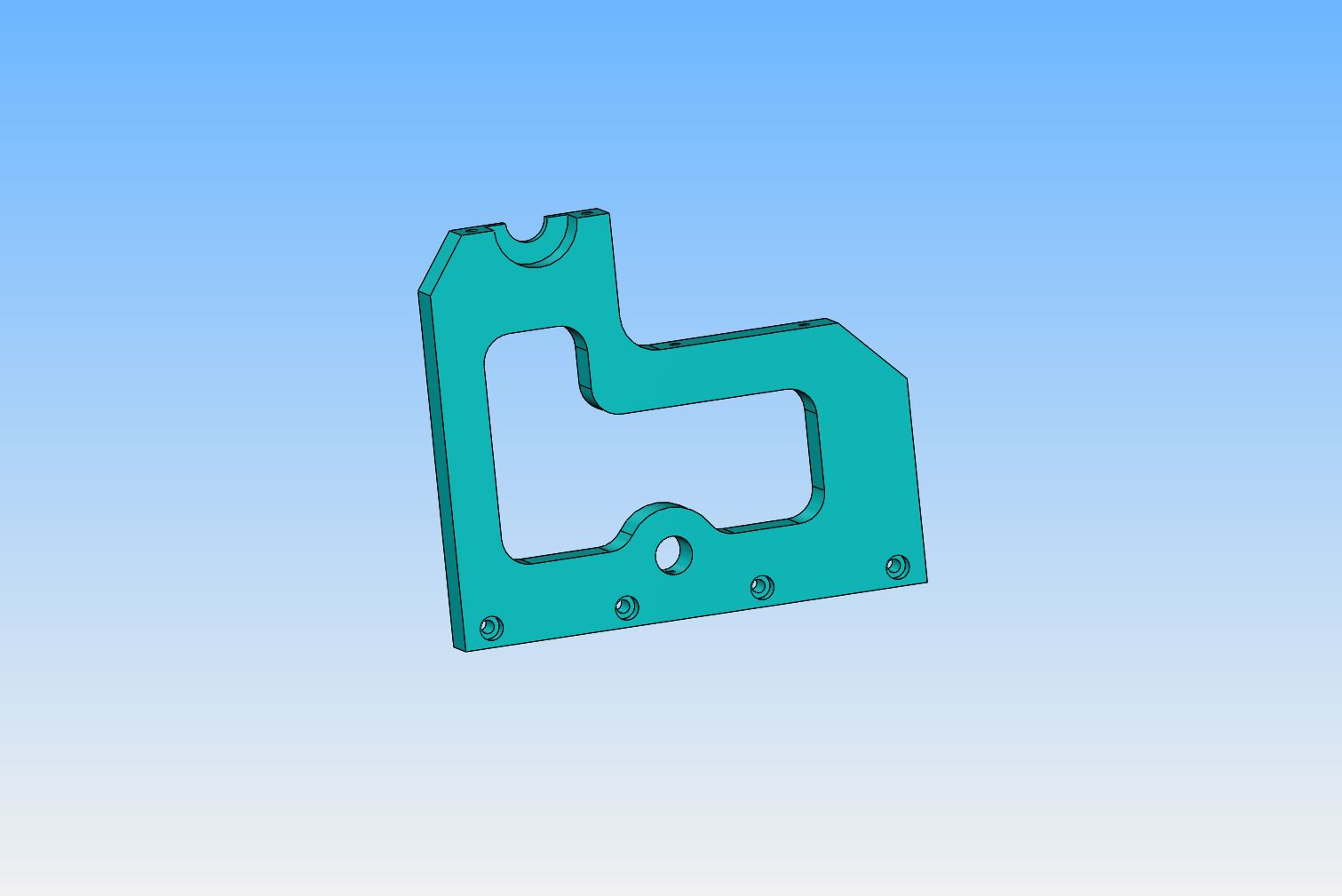
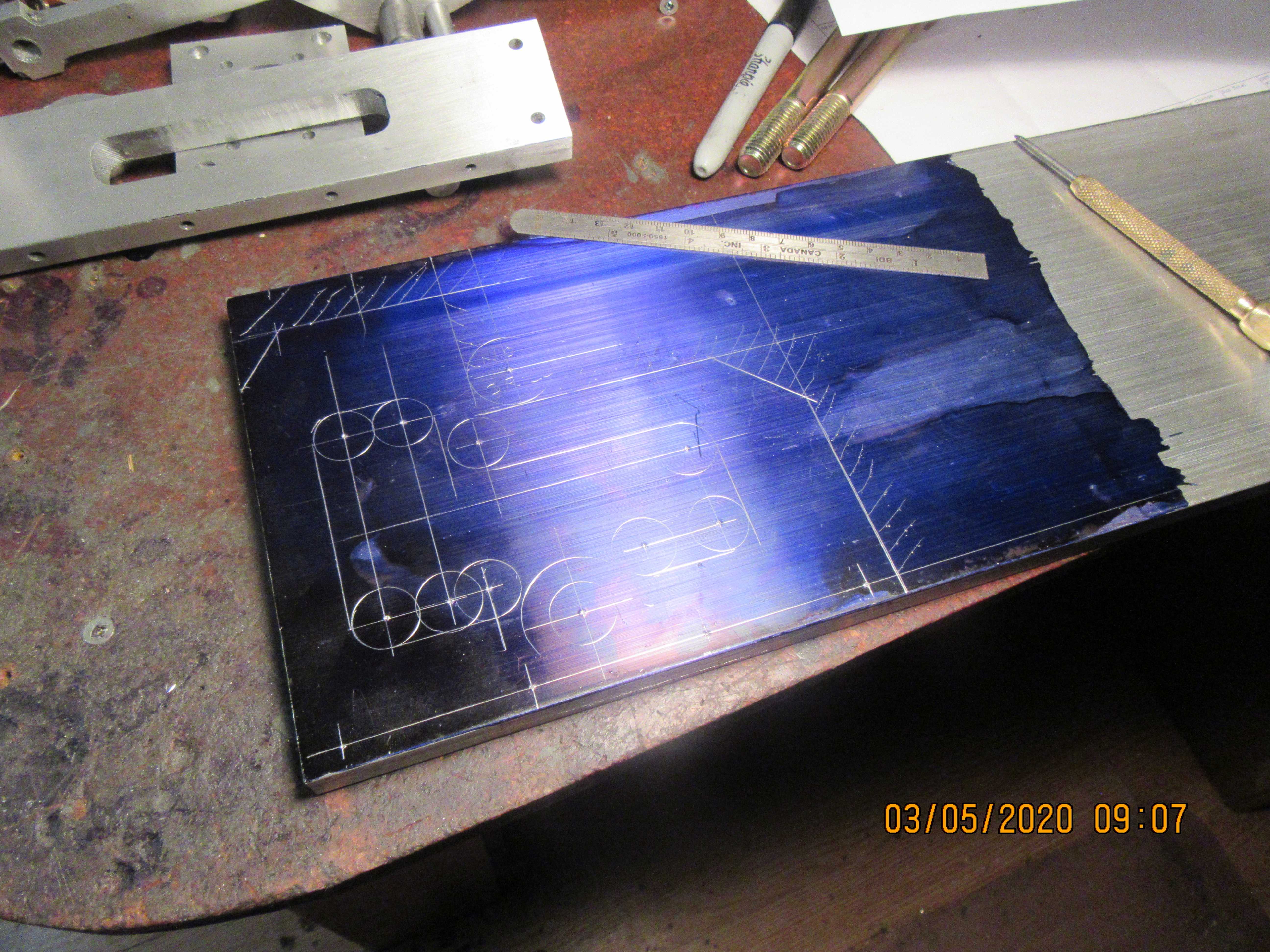
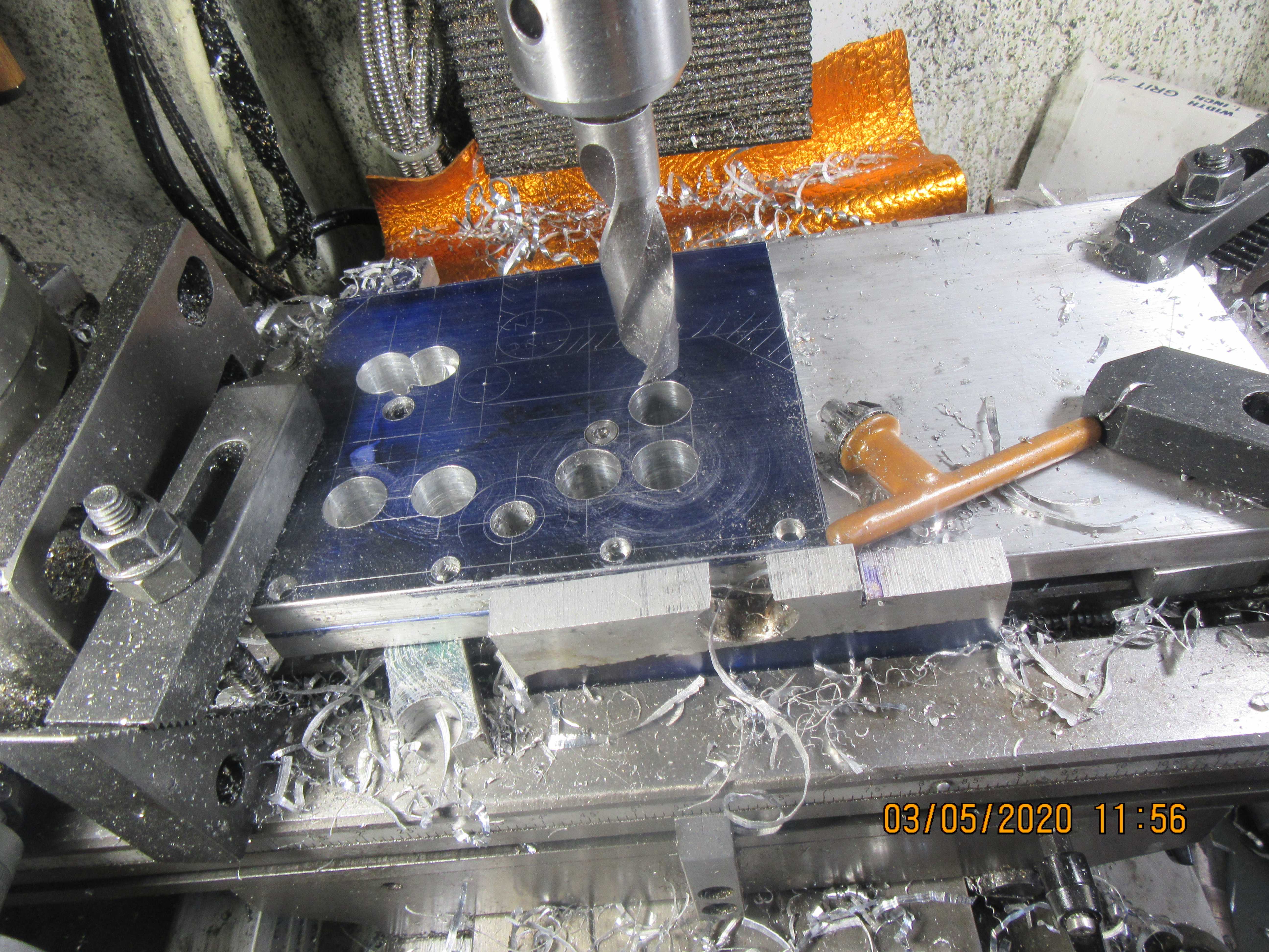
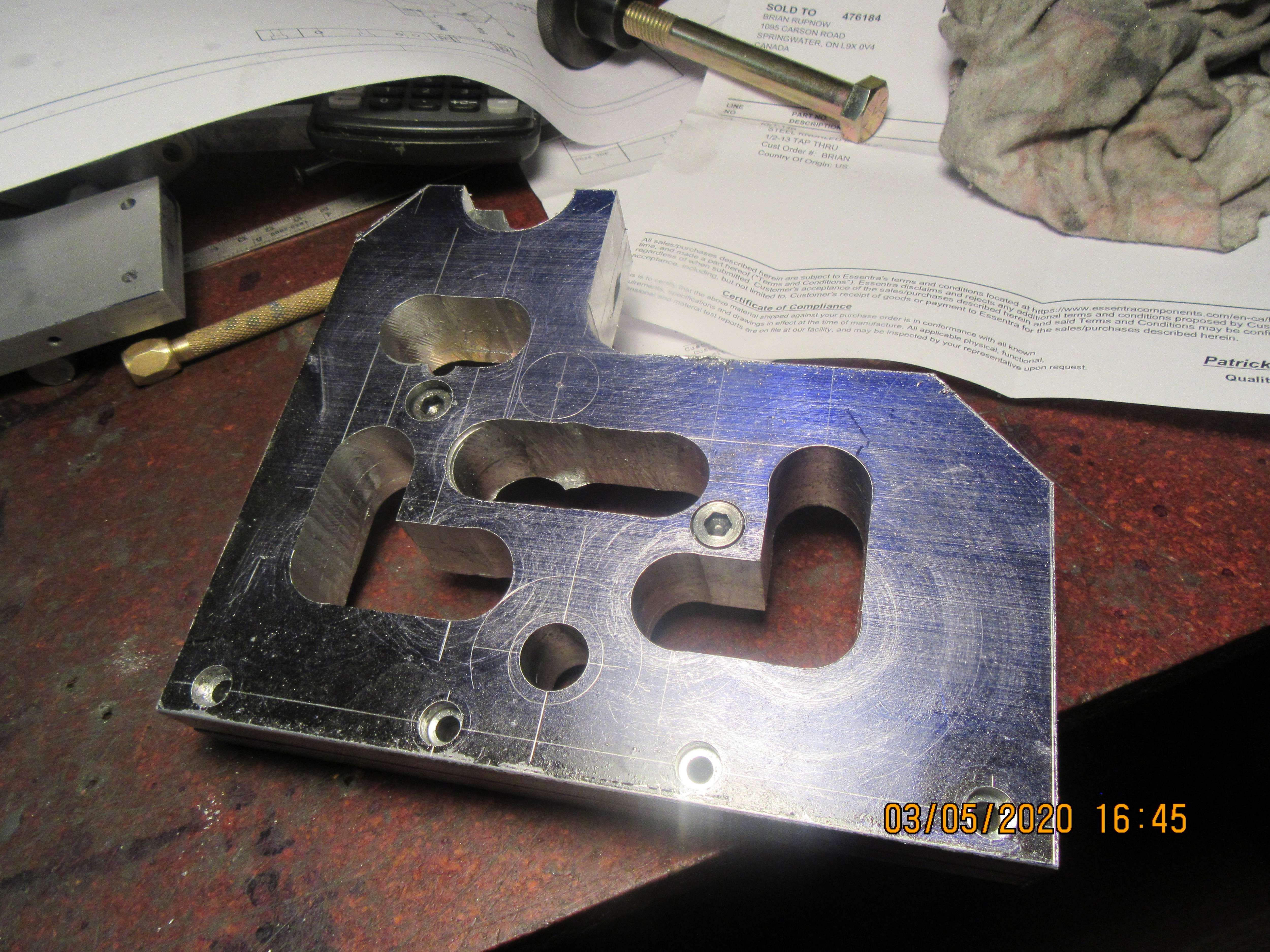
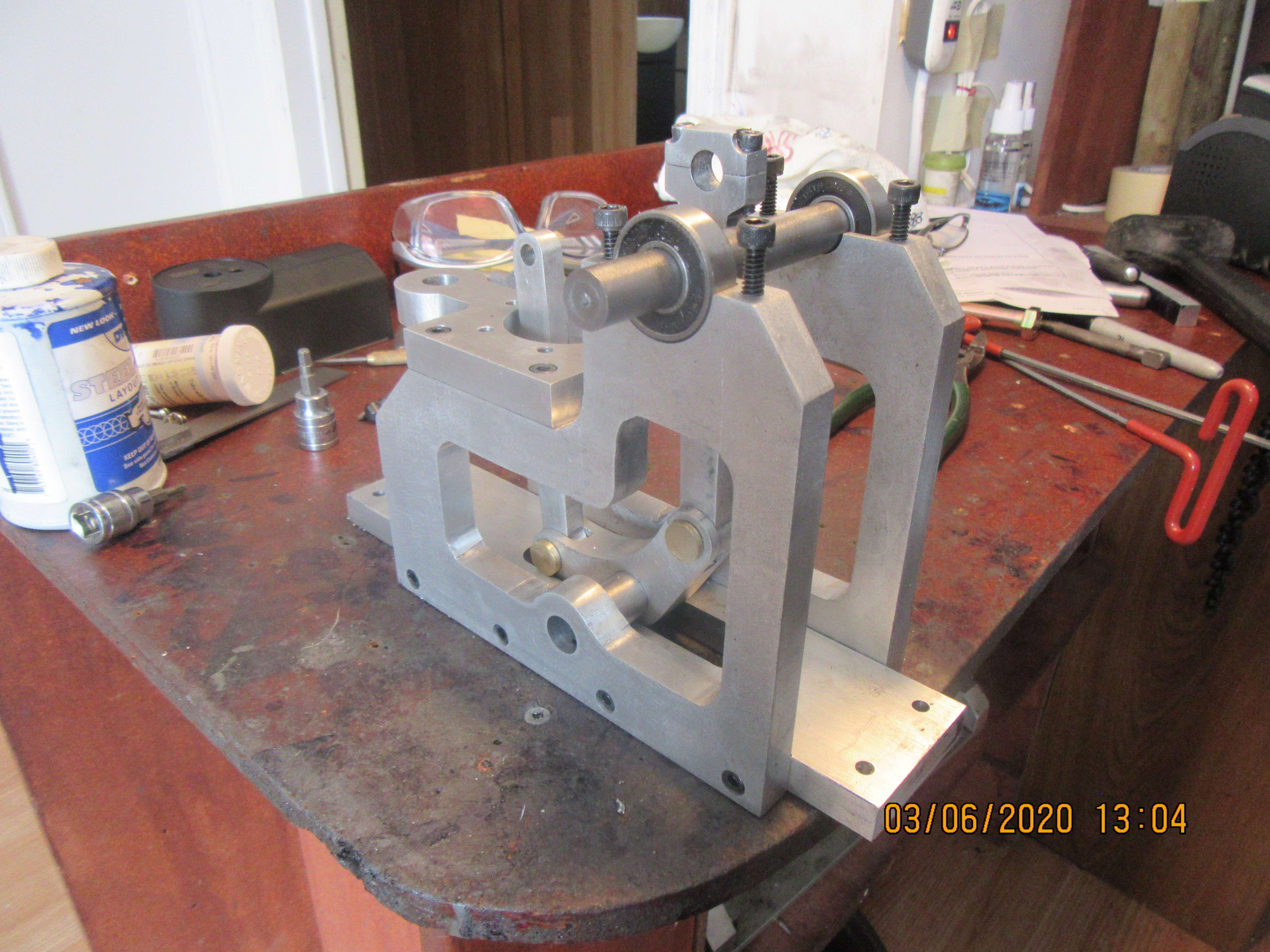
Tomorrow I will designate as "Side plate day". The side-plates are pretty well identical, except that the counterbored holes make them right and left hand. It is much less work if I can do all of the profile work on both plates at the same time. I will bolt the plates together , putting the connecting holes somewhere in the center area that gets milled away as a "last step". One plate will be drilled and tapped, the other will have countersunk or counterbored holes in it so it will lay flat. even the counterbored holes can be put in---When I separate the plates the bottom plate can be flipped over and counterbored.