I've spent much of today "dialing and tweaking" to see how slow I could get the engine to idle. It idles at about 950 to 1000 rpm with no load at all on the engine, and idles at 800 rpm quite happily with the load of a driven clutch on it. If I try for anything lower than that, it just gives up and stalls.

You are using an out of date browser. It may not display this or other websites correctly.
You should upgrade or use an alternative browser.
You should upgrade or use an alternative browser.
Thumper--a 1 3/8" bore i.c. engine
- Thread starter Brian Rupnow
- Start date


Help Support Home Model Engine Machinist Forum:
This site may earn a commission from merchant affiliate
links, including eBay, Amazon, and others.
- Joined
- Oct 1, 2010
- Messages
- 1,340
- Reaction score
- 393
Great to see and hear it running, Brian.
Speed seems to sound about the same as some genuine antique engines working that I have heard.
Thank You for all your posts.
--ShopShoe
Speed seems to sound about the same as some genuine antique engines working that I have heard.
Thank You for all your posts.
--ShopShoe
- Joined
- Sep 2, 2011
- Messages
- 1,340
- Reaction score
- 355
Brian, that sure is a nice engine you have built. congratulations on yet another fine runner. curious about the air flow the fins in the fly wheels create, alot, some or ??? you may have said something in the videos but i cant play them with sound on so i dont know. but it seems to run slow enough for me to be able to watch the valves in action which is nice.
Werowance--they do move a lot of air. And just as I suspected, the air is drawn into the "fans" not in a direct line, but in a funnel shape. This means that there is a lot of air turbulence around the cylinder. I'm pleased with the volume of air that the "fans" move.---Brian
Hi Brian
Interested in how well your engine is balanced when running. As with allot of scale model engines they need to be bolted to a stand/base board or sometimes clamped to a table top. Have you tried running your engine unrestrained? I am thinking that it's layout should result in a smooth runner.
Cheers
Willy
Willy---I clamp or screw-nail all my engines down before trying to start them. I use my variable speed electric drill for a starter. If an engine floods and hydro-locks you can watch six or eight weeks of work go flying onto the cement floor and smash to pieces if the engine isn't securely held down.
I've spent much of today "dialing and tweaking" to see how slow I could get the engine to idle. It idles at about 950 to 1000 rpm with no load at all on the engine, and idles at 800 rpm quite happily with the load of a driven clutch on it. If I try for anything lower than that, it just gives up and stalls.
Hi Brian and whoever is interested, Your engine is ticking over fine Great Job. I have uploaded a video to Youtube, thanks for watching, Ted
Hi Brian and whoever is interested, Your engine is ticking over fine Great Job. I have uploaded a video to Youtube, thanks for watching, Ted
So I have again unsuccessful with my post, I will try again maybe another video.
Ok this is the real Inspectors Motor Trolley. No history is available except there is a brass tag attached saying it was brought down to the Ipswich Rail Museum Queensland Australia from Normanton Far North Queensland in 1973. It is an all wood design even the wheels have wooden spokes. A close look at the engine reveals several clues to its age, no carburettor just a hollow box, only speed control is a lever to hold the exhaust valves open, buz coil ignition, no spark plugs as we know them, no cooling fins. The engine is Fairbanks Morse and obviously runs very slow ie 100 RPM = 15 MPH the trolley uses the flywheel as the driving wheel. This is 1880s technowledgy. It is possible that it was used during the building of the Normanton to Croyden line 1889. In use it was pushed along the line and when up enough speed driver had to jump aboard and release the valves.So I have again unsuccessful with my post, I will try again maybe another video.
Attachments

Hope this one works, Must apologize for the dog wanting to get in on the action.Ok this is the real Inspectors Motor Trolley. No history is available except there is a brass tag attached saying it was brought down to the Ipswich Rail Museum Queensland Australia from Normanton Far North Queensland in 1973. It is an all wood design even the wheels have wooden spokes. A close look at the engine reveals several clues to its age, no carburettor just a hollow box, only speed control is a lever to hold the exhaust valves open, buz coil ignition, no spark plugs as we know them, no cooling fins. The engine is Fairbanks Morse and obviously runs very slow ie 100 RPM = 15 MPH the trolley uses the flywheel as the driving wheel. This is 1880s technowledgy. It is possible that it was used during the building of the Normanton to Croyden line 1889. In use it was pushed along the line and when up enough speed driver had to jump aboard and release the valves.
Attachments


Now we get to talk about cam timing. As you can see in the drawing, there is about 125 degrees of "cam influence". That gets doubled when you think of what is happening at the crankshaft, because of the 1:2 ratio between the crankshaft gear and the camshaft gear. So---at the crankshaft we have 250 degrees which we have to account for. When the piston travels full stroke from top dead center to bottom dead center, that accounts for 180 degrees. so 250-180=70 degrees. I like to have the intake valve start to open about 20 degrees before the piston reaches top dead center on the exhaust stroke. I can adjust the cam position to make this happen. If we take that 70 degree figure and subtract the 20 degrees from it, then that means that the intake valve will close 50 degrees into the compression stroke.--I can't set that last figure. That last figure is totally dependent on the shape of the cam. I like my exhaust valve to begin opening at 45 degrees before bottom dead center on the power stroke, and I can set that. So, again, if you subtract that 45 degrees from 70 degrees, that means that the exhaust valve stays open until 25 degrees into the intake stroke. I will set the cams up as written in the text, and see what happens. These calculations do not take valve lash into account, but they seem to work for me when the valve lash is set to about 0.010".
Brian, valve timing is something that I feel like I only barely understand. Any words of wisdom to offer on how you came up with the 125° angle of action and the 20° BTDC / 45° BBDC settings at which the valves begin to act? Or any reference works that have been particularly helpful to you as you have designed your engines?
Last edited:
Valve timing is a black art. I have read many articles dealing with it, and I only understand about 30% of what I have read. I can't give you any particular reference texts, since I have been reading various and sundry articles about it for many years. Basically, it goes something like this. In a world of pure theory, the intake valve would spring open at exactly the beginning of the intake stroke, spring closed exactly at the bottom of the intake stroke, and the exhaust valve would spring open exactly at the beginning of the exhaust stroke and spring shut at the end of the exhaust stroke. However, in the real world, we have inertia and time to deal with. The valves don't really "spring" open or closed. They need to gradually ramp up from fully closed to fully open, and vice versa. They may even have to "dwell" in the opened or closed position for a split second. Also, considering inertia, the charge of fuel and the charge of exhaust both need a little time to start moving. To compensate for inertia, the intake valve can actually begin to open slightly before the beginning of the intake stroke, and can even remain open part way into the compression stroke. The exhaust valve can begin to open during the power stroke, remain open all the way thru the exhaust stroke, and even during the first bit of the intake stroke. The point at which the valves proceed to open and to close are determined by the profile of the cam. The profile of the cam is determined by how fast the engine is designed to run. This opening before and after the theoretical tdc and bdc are referred to as valve lead and valve lag. The faster the engine is designed to run, then the more lead and lag will be designed into the cam because everything has to happen in a much shorter period of time. I have built many engines, and I more or less know what will work and what won't work for a fairly low speed engine such as I have designed here.
Thanks, Brian. I feel reassured that I am not the only one who finds it to be less than clear. I'll claim maybe 5% understanding of what I have read ... but I can easily follow someone's example, and you clearly have just a bit of experience ... ")
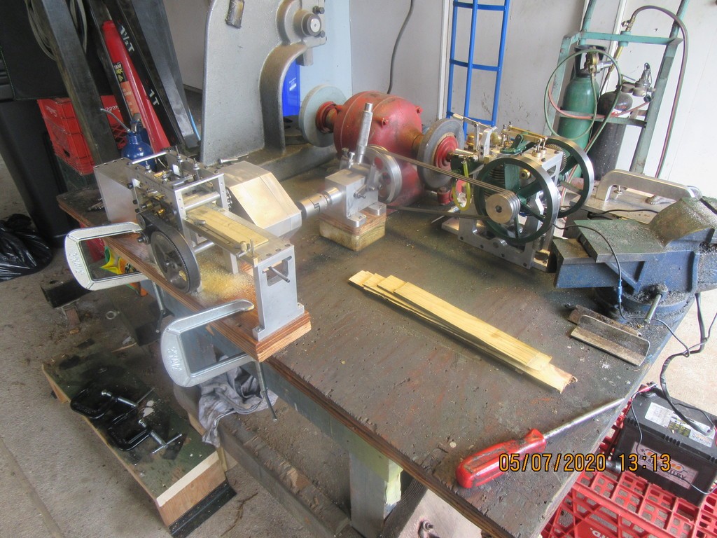
So---What was the outcome of this exercise? Not what I would have liked, but I will explain. "Thumper", with it's larger bore is a lot more powerful than any of the other 1" bore engines that I tried to run the sawmill edger with. I can easily start the engine with the disengaged clutch driven by three rubber o-rings. With no o-rings in place, the engine idles at around 1000 rpm. With the load of the o-rings driving the clutch (while it is disengaged), the idle rpm's drop to about 800 rpm. However, the edger is designed to have an input of 2000 rpm driving the 16:1 gear reducer. This should turn the saw-blades at 1000 rpm, and turn the infeed rolls at a lower rpm so as not to over-run the saw-blades. I adjusted the engine to run at +/- 2000 rpm, and engaged the clutch. The engine took it all in stride, and didn't stall. There was a noticeable drop in engine rpm, but it drove the edger mechanism without any noticeable bogging. However, when I went to feed a board through the edger, the board would get about half way thru the saws, and then stall the engine. I repeated this about 10 times with different settings and adjustments, but it became plain that the new engine simply didn't have enough power. I have a theory, but at this time it is only a theory. With the ignition set to fire at 15 degrees before top dead center, the engine starts and idles very smooth, and revs up very well in response to opening the throttle. I have the feeling that at 2000 rpm, the timing is too slow for that rpm. The engine doesn't have any mechanism to advance the spark timing with changes in engine rpm. I believe that if I were to modify the engine so that as the throttle opened the ignition timing would advance automatically, the engine would be much more powerful at the 2000 rpm it is being asked for. I have decided to back away from this project for a while and do something else. I will probably come back to this and redesign the engine to give it an automatic spark advance, but for now I'm burned out on it.
stragenmitsuko
Well-Known Member
- Joined
- Jan 19, 2016
- Messages
- 326
- Reaction score
- 143
There are electronic programmable spark controllers available .
Mostly used in performance engines but I can't see why it wouldn't work on a model .
It takes a trigger wheel on the crank wit a nmbr of teeth . Typical 36 .
And a trigger on the cam to tell when the engine is in it's compression stoke .
Most of them will also accept a map sensor to measure engine load .
And it's all glued together with electronics and software .
Pat
Hi Brian. Engine looks and sounds great , sorry to hear you are having trouble with driving the saw edger . Just a thought and I can't see any governor connected to the throttle . As the RPM drops off you want the governor to open the throttle similar to a flyball governor on a steam engine to maintain RPM . Most small engines on lawn mowers , riding tractors , snowblowers etc . adjust the throttle under load and the ignition timing stays constant .
Just a thought .
Bill
Just a thought .
Bill
Last edited:
Payner--This engine has no governor, but before I made my trials with it I had turned the throttle adjustment screw in to the point where the engine was running at about 2000 rpm. The edger grabbed the board and sent it through the first set of powered rollers, then about 3" thru the saw, and then when the board got to the second set of rollers the engine bogged down and quit. I will retry it later this week with a weaker set of springs on the last set of powered rollers.---I have also investigated adding a manual ignition advance. It can be easily done, but I've hurt my back and I'm setting here designing with a heating pad on my back.
Last edited:
Brian . That's the point I'm trying to make , your throttle should be connected to a governor. Set your RPM to 2000 ( no load ) as you load up the engine with the wood going through the saw , the RPM will drop , the governor will open the throttle to maintain the 2000 RPM . When the cut is finished and the RPM starts to increase the governor will start to close the throttle and maintain your 2000 RPM .
All small engines work this way except some outboard motors , they don't vary ignition timing like a car .
Bill
All small engines work this way except some outboard motors , they don't vary ignition timing like a car .
Bill
Last edited:
I am sorry it didn't give you the power you thought it would right off the bat.So---What was the outcome of this exercise? Not what I would have liked, but I will explain. "Thumper", with it's larger bore is a lot more powerful than any of the other 1" bore engines that I tried to run the sawmill edger with. I can easily start the engine with the disengaged clutch driven by three rubber o-rings. With no o-rings in place, the engine idles at around 1000 rpm. With the load of the o-rings driving the clutch (while it is disengaged), the idle rpm's drop to about 800 rpm. However, the edger is designed to have an input of 2000 rpm driving the 16:1 gear reducer. This should turn the saw-blades at 1000 rpm, and turn the infeed rolls at a lower rpm so as not to over-run the saw-blades. I adjusted the engine to run at +/- 2000 rpm, and engaged the clutch. The engine took it all in stride, and didn't stall. There was a noticeable drop in engine rpm, but it drove the edger mechanism without any noticeable bogging. However, when I went to feed a board through the edger, the board would get about half way thru the saws, and then stall the engine. I repeated this about 10 times with different settings and adjustments, but it became plain that the new engine simply didn't have enough power. I have a theory, but at this time it is only a theory. With the ignition set to fire at 15 degrees before top dead center, the engine starts and idles very smooth, and revs up very well in response to opening the throttle. I have the feeling that at 2000 rpm, the timing is too slow for that rpm. The engine doesn't have any mechanism to advance the spark timing with changes in engine rpm. I believe that if I were to modify the engine so that as the throttle opened the ignition timing would advance automatically, the engine would be much more powerful at the 2000 rpm it is being asked for. I have decided to back away from this project for a while and do something else. I will probably come back to this and redesign the engine to give it an automatic spark advance, but for now I'm burned out on it.
Loren---I am too. I have a couple of more tricks up my sleeve. This isn't dead yet. I'm just leaving things until my back feels a bit better.---Brian
Similar threads
- Replies
- 62
- Views
- 13K
- Replies
- 1
- Views
- 1K