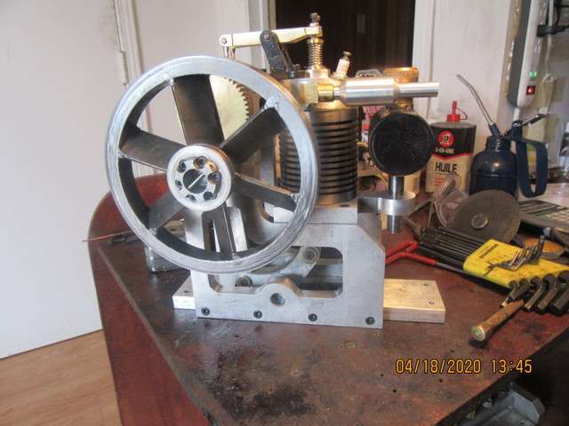
Thumper--a 1 3/8" bore i.c. engine

Home Model Engine Machinist Forum

Help Support Home Model Engine Machinist Forum:

This site may earn a commission from merchant affiliate links, including eBay, Amazon, and others.
Today I welded up one of the flywheel fans. Let me be the first to say its uglier than original sin!! However, I haven't done any clean up on it yet. I've welded it in all of the spots (4 per blade,) that I intended to. I didn't melt anything away, although I probably added three times as much filler rod as I needed to at every spot. There seems to be only micro-seconds between having the metal molten enough to 'merge' with the filler weld and so hot that you burn away the fan-blade. I tried it with a 1/16" tungsten and filler rod at 70 amps max and with 3/32" tungsten and filler rod at 115 amps max. I am dazzled by how quickly everything happens. Back in the day, I did a lot of oxy-acetylene welding, and since I controlled the torch, things only happened as fast as I wanted them to. With this TIG process, it keeps wanting to run away on me. It gets so hot, so quickly, and gets molten so quickly that I'm afraid I'm going to melt everything before I get a chance to add any filler rod. Next step will be to clean everything up and decide if I want to add any more weld anywhere.
 
Is your pedal working??
Because if you throttle back on the pedal you should be able to get the amps back to nothing and barely have an arc.
The pedal should control from zero to whatever you have dialed in as maximum.
Down to the point nothing melts and the little arc just sits there at the end of the tungsten.
Sounds to me like something is wrong. Certainly nothing should be "running away from you".
Also there should be no clean up required. Tig welds are very clean right off the torch.
 
Andy. I have an old analog machine that's always zero at minimum pedal.
Dang fancy new machines have too many variables :).
Nice to know. Thanks.
But yes. I can sit with a tiny little sparkle at the end of the tungsten that barely heats anything. Something has to wrong there.
 
Dave, it may have been on the other forum that Brian showed a picture of his pedal. I've never seen one like it - he has two potentiometers on it, one to set the minimum setting and one to set the maximum setting. I've seen pedals with a potentiometer to set the max - a less convenient option than being able to dial it in on the machine itself, but better than nothing. This is the first time I have seen a second pot to set the min, and I still can't figure out why that would be useful.

I've got a brand new semi-digital machine with lots of bells and whistles - semi-digital meaning that it uses digital controls internally, but analog knobs to set the settings - but like yours, minimum pedal always equals zero amps!

On edit: see reply # 172 in this thread for a picture of the footpedal: Thumper--a new 1 3/8" bore i.c. engine
 
I sat around after my welding, trying to analyse what was happening. I decided that it must have been the foot pedal. It wasn't the fault of the pedal. It was just the way I was using it. Ran things with the pedal "on the floor". Tomorrow I will try some welding with more of my attention on what position I am holding the pedal in.
 
Brian, I would recommend spending a bit of time practicing just with the foot pedal and the arc - you should, as Dave says above, be able to go from a tiny firefly to a high-power arc and back again, and anywhere in between. If this doesn't work, I'd start to suspect that something is wrong with your machine. :(
 
-I needed a bit of filler rod. All of the "blades" had a 3/32" x 45 degree chamfer on them. This was so I could fill the chamfer with filler rod, and then when I cleaned everything up afterwards I could be certain that all of the blades were indeed still welded. I have cleaned the first flywheel up on the lathe and mounted it, along with the starter ring on the engine. I am very happy with the size and proportions. I think that after the second flywheel is welded, that I may paint both flywheels and just leave the outer diameter unpainted.
pVmkVe.jpg
 
That looks good !!
Maybe -- if you care to and it actually needs it -- a little grinding with a dremel and a bit of body work and paint on the spokes and inner ring and you can gussy it up.
It's getting there :)
 
It's too cold and damp to work out in the main garage with my tig welder today. So--Just to keep things moving forward, we install ignition points today. There was no need to dismantle the engine to add these two tapped holes. I have a big old cast iron angle plate that lets me bolt the angle plate to the mill bed and clamp the fully assembled engine to the angle plate. With the end of the crankshaft sticking up past the plate, it is great to have some extra long drills and taps. I will find a spot to attach the condenser while I am still in this set-up. The points will be hidden in behind the flywheel. Not exactly sure about the condenser location, but will find out in the next half hour.
wAhrlK.jpg
 
Andy---Near as I can tell from a static balance, the flywheel is fine.
The condenser was just a tad to big to fit behind the flywheel, so I moved it's location around to the end of the sideplate. And that is the sum total of the electrical components for this engine. Nothing left now except for the second flywheel. I just got back from my "fat mans walk" with my good wife, and we got rained on! I judge that I've got about 1 week of entertainment left on this engine, and then I may go stark raving mad. I've been entertained by this engine thru March and April, so that has given me something to do. I will definitely need a few weeks away from machining. This down time between builds is generally when my wife and I took time for each other and our grandkids. Now with this virus business, you can't really go and visit friends and you can't do things with grandchildren.
HZhUKY.jpg
 
When I design and build these engines, I don't make an assembly drawing, only parts details---I work directly from the cad assembly on my computer. Of course when I decide it's time to sell plans, then I need to make complete assembly drawings so people who buy them know how to assemble them. The plans are never sold before the engine works to my satisfaction. I needed some quiet time this morning while my wife sleeps, so I've went ahead and made assembly drawings.---Brian
tOzb7n.jpg

A46wvD.jpg

0FCpvr.jpg
 
Hi Brian:
On welding the fins, let me tell you how I was able to get run a .020" bead on the side of a mild steel block.
I was trying to weld the smallest spring wire I could purchase (.008") for a job. I never was able to do it but like
I said I did get the weld bead down to a .020" by shutting off the high freg. and just cracking the amp. control
so that the led indicated it was on and using a .020" Tung., Then using a bright light shining on the work so I could
see the work I carefully put the peddle to the metal on the foot peddle and slowly brought the tung. toward the edge
of the work till I got an arc. I then was able to work the puddle down the edge of the part.
I think if you work the heat like you did with a torch starting low and working up you will have a whole different
weld. The main reason, I think, is that the tig welder gives instant heat and if you use the higher amp they recommend
for a material thickness that is enough heat to go all the way through the material. Welding the fins from both sides,
I think, only needs half as much because you are only welding one half the thickness of the metal. Just my 2 cents.
(Not worth much these days)
Bill Thomas
Stuck inside in Michigan, USA
 
Hi Brian:
Just sitting around thinking about you welding today. You said earlier about not needed a tig torch to build the engine.
I have been thinking about how you would Silver Solder the flywheel to make it strong enough and safe. If you have not tig
welded the second flywheel have you though about how you could Silver Soldering it together. You have it fixtured good
so you could run a fillet bead each side of the blade with a small Acy torch. Just thinking while stuck inside.
Bill Thomas
 
Bill--the biggest problem with welding the blades using oxy-acetylene would have been distortion of the metal. Wobbling flywheels show up big time in videos. There was some distortion from the tig welding. I had the inner hub and outer ring fixtured perfectly, but still got some heat distortion. I think that when I mounted the flywheel on a 1/2" shaft with the shaft in my lathes 3 jaw chuck I had about .017" distortion on the sides of the outer rim and about .015 on the outer diameter. I cleaned up both sides and the o.d. so that the flywheel runs perfectly true now. The biggest issue would have been adding enough heat into that outer rim to get silver solder or brazing flowing on it. I like my mig welder, but its almost impossible to get a bead that is pretty enough on small items without having to resort to filing and sanding and grinding. I've been thinking of buying a tig welder for a couple of years now, and these strange flywheel/fans gave me an excuse to buy one.
 

Latest posts

Back
Top