Throttle governed engine

Home Model Engine Machinist Forum

Help Support Home Model Engine Machinist Forum:

This site may earn a commission from merchant affiliate links, including eBay, Amazon, and others.
You may remember that I made up a narrow 1/16" wide knurling roller to put a knurled finish in the bottom of o-ring slots on the pulleys I make. This was in order to keep the pulleys from slipping as they drove an o-ring used as a drive belt. I haven't used it before, but this morning I decided to do both driver and driven pulleys on the governor drive. this is what the knurled slot looks like.
HWKbXR.jpg
 
How exciting!!! I have the engine running and the governor is operating and very sensitive. I haven't got things to the point where they are consistent enough to make a video, but it works. The engine is not terribly sure that it likes the additional load put on it by the governor system. I can take the o-ring drive off, and the engine runs quite fine. I put the o-ring belt back on, and the engine wants more throttle to run with the additional load. As it is running, I can see the governor weight system moving in and out against the tension spring and moving the throttle, seeking it's "happy spot". I have my office door open to keep from gassing myself, and it's colder than a witches tit in my office. Going to quit now and have some lunch, and try to get the grin off my face.
 
A couple of short videos. I'm not finished yet, and there is a blizzard raging outside my office door, so I can't run the engine very long without having my door open. The fact that the engine runs and the governor is trying to do it's thing is quite positive. I am expecting to have better results as I refine things a bit. There is more governor action in the first video clip than in the second. I think I had the governor locked in position on the second run.

 
Okay, third times a charm, and this is probably where I will quit for the day. The governor is working and controlling the throttle on the carburetor. I'm sure I have more tuning to do, and that arm which holds the end of the tension spring is going to need an arrangement to make it far more adjustable. I have to think on that one for a bit.--Probably need to make it adjustable with some kind of threaded screw to get fine adjustment. At any rate, concept is proven, and I like it.
 
I probably burned up a few brain cells thinking of this--I want to turn the red threaded knob to move the green threaded rod to tension the spring---but I don't want the green threaded rod to turn. If I put a flat on each side of the threaded rod, and a slot instead of a round hole in the beige colored bracket, that should do it. This will let me fine tune the tension on the spring to give correspondingly finer tuning of my target engine rpm.
9P1qsQ.jpg
 
And---On the weirdness-ometer-- I seen a dog wearing snow boots today. There is a foot of snow here, and it was a rotten day outside, so I went up to the Georgian shopping mall for my "fat man's walk". (Four laps around the mall=1.6 miles.) People take service dogs in training up to the mall. I seen a half grown German Sheppard dog, wearing a dog coat (I've seen dog coats before) and a set of pretty blue snow boots!!! I commented on it to the trainer, and she told me that "All the dogs are provided with snow boots in inclement weather." The dog didn't seem to mind the boots at all!!! Hey---I want to live another seventy three years---I'm still seeing new things that I've never seen before.
 
This morning I built the fine adjustment bracket and flat sided 1/4" threaded part exactly like the 3D cad and it all works fine. I re-used the knurled nut? that originally held the first spring tension lever in place. Now I'm at a point where there is nothing more to make. Now it gets down to the hard part of making it all work in harmony. I shouldn't admit this, but I enjoy making the parts way more than actually getting everything to work. I have a fairly good success rate of getting things I design to work, but there are times when I wish I had George Britnell and Chuck Fellows standing here in my office to bounce ideas off of. Getting small engines to perform is 70% engineering, 20% experience, and 10% magic. Probably tomorrow I will take the drive belt off of the governor and set the engine up to run as well as it can without the governor. Recheck the ignition timing, the valve timing, and the carburetor needle settings. Once I have worked thru that, I will put the governor drive belt back on and make any necessary adjustments.
5KbtKe.jpg
 
I'm feeling a bit under the weather today, so no real work, just a lot of heavy thinking. George Britnell had mentioned that these small engines don't really like to start with a wide open throttle, and I agree with him. That is why I made the sliding affair with the pull knob that could be used to over-ride the governor and lock the carburetor in it's "closed" position for starting. However---I have found that when cranking this engine with my electric drill that the governors are very sensitive and as soon as I start to turn the engine over, the weights fly outward and put the carburetor into "closed" position anyways. Although this style of carburetor does have an internal "idle adjustment screw" which actually limits how far the throttle closes it is giving me problems. Without changing the complex bracket that holds this sliding affair with the pull knob, I can replace the bolt on top-cover and have room to install a 1/4" threaded rod with a knurled end on it to act as the throttle stop. This will actually work against the throttle lever arm, instead of being part of an internal throttle stop. I have a good view right down the carburetor throat the way this carb is mounted, and much better accessibility to adjust the throttle stop to a point where the engine idles but doesn't die out and stall. (The carburetor is hidden in this view, with only the throttle arm being visible).
jQ4sv6.jpg
 
I have made the changes outlined in the last post. Engine runs, but not happily. I am in the middle of removing the home made carburetor and putting on a purchased Traxxas carburetor. This is more of a quick and dirty diagnostic than anything. Self throttling feature will not run with Traxxas carburetor, however if the engine runs well with the Traxxas, then I know the home made carb isn't working properly. If behavior doesn't improve, I will have to dig deeper. The videos on Youtube had the links pasted in this thread. The Traxxas 4033 carburetor is just about the perfect size for large single (1" bore)and smaller (7/8" bore) twin cylinder engines. If I have any complaint at all about them, it is the fact that the side which attaches to the intake is a plain 10 mm outside diameter. This means that any time you want to use them, you have to make a simple adapter like the one shown here. I use a bit of 638 Loctite to attach the carb into a reamed 10mm hole in the adapter. I'll let the Loctite dry overnight and see what happens with the engine tomorrow. The governor has been disconnected by slipping the o-ring drive belt off the engine pulley.
vEQj6I.jpg
 
Last edited:
The engine did run with the Traxxas carb on it, but it didn't run consistently. I discovered it had a plugged gas line right where the line enters the gas tank. Even after I had cleaned out the blockage it wouldn't run consistently. Finally, I tore the engine down completely. I was really trying to avoid that, but ya do what you have to do. I decided that first order of the day was to replace the viton O-rings. I don't think they were the problem, but since I have everything apart that is what I will start with. The two old rings are on the left of the picture, the two brand new ones on the right. In case you were wondering---I hate this worse than snakes!!! I like to build an engine, tune it, run it, make a video of it, then move on to something else. This going back and conducting a post mortem on an engine which no longer runs the way I want gives me a big pain in the head.
z0Cy0i.jpg

jox9wh.jpg
 
Engine has been reassembled with new rings. This complete disassembly has given me a chance to clean everything up and to get rust and crud off the fins of the cylinders. I found that the set screw holding one wrist pin in place had fallen out, but fortunately the pin hadn't drifted sideways and scored the cylinder wall. I don't use aluminum outer cylinder with a cast iron liner. I make the entire cylinder from one piece of cast iron. That way it is much less work, better heat dissipation, and all I sacrifice is a bit of pretty. Tomorrow as I reassemble things I will check valve and ignition timing. The engine is so clean and new looking now that it is rather startling.
 
I may have found the culprit. The old rings were worn, but not to the point where the engine was losing compression, so they were probably doing their job just fine. However, as I proceed with the re-assembly, I have found that the adjuster for the intake valve on the right hand cylinder bank was way, way out of adjustment. It had backed off to the point where just the very tip of the cam was "grazing" the lifter. I had labelled the push-rods as I disassembled the engine, so they haven't been mixed up. I will reset all of the valve adjusters now.
 
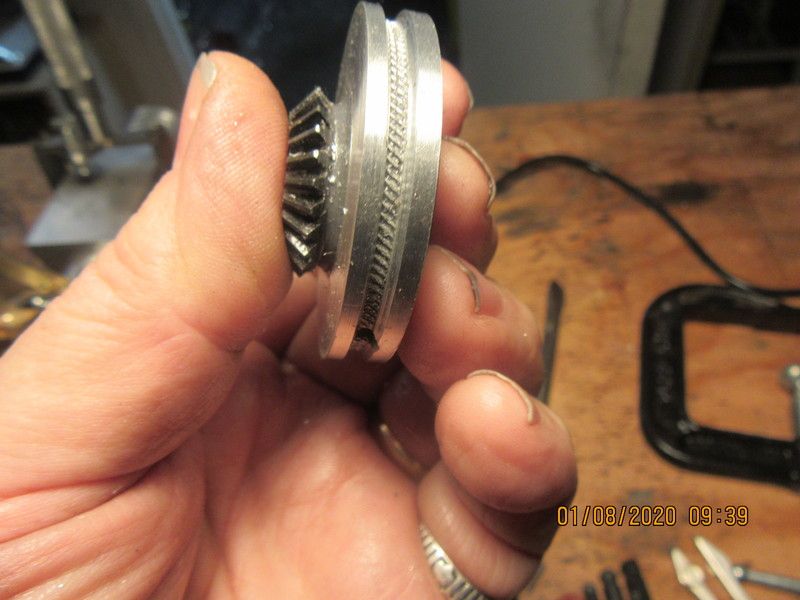
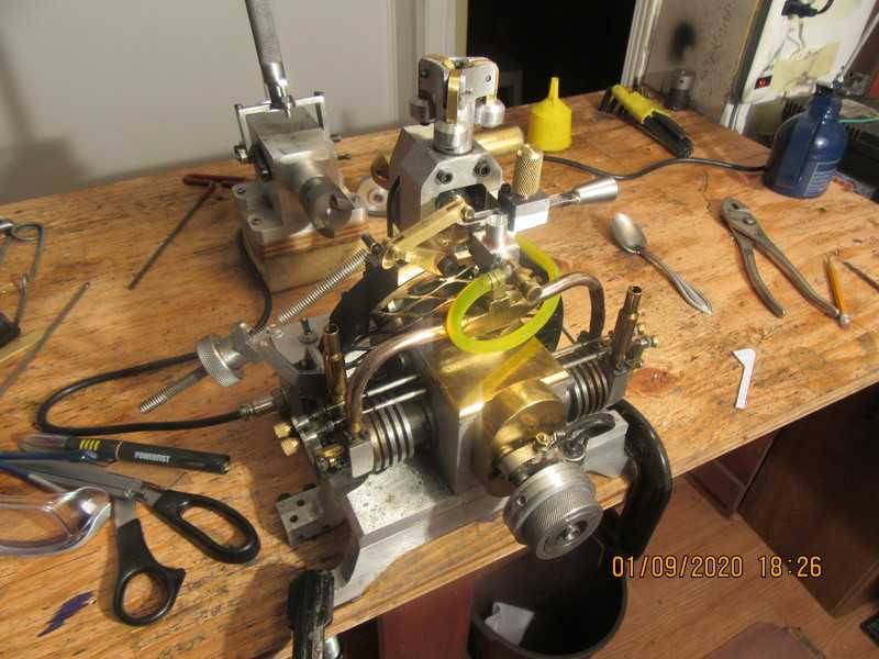
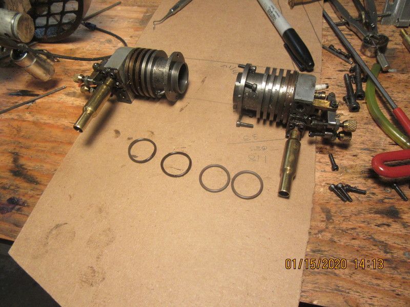
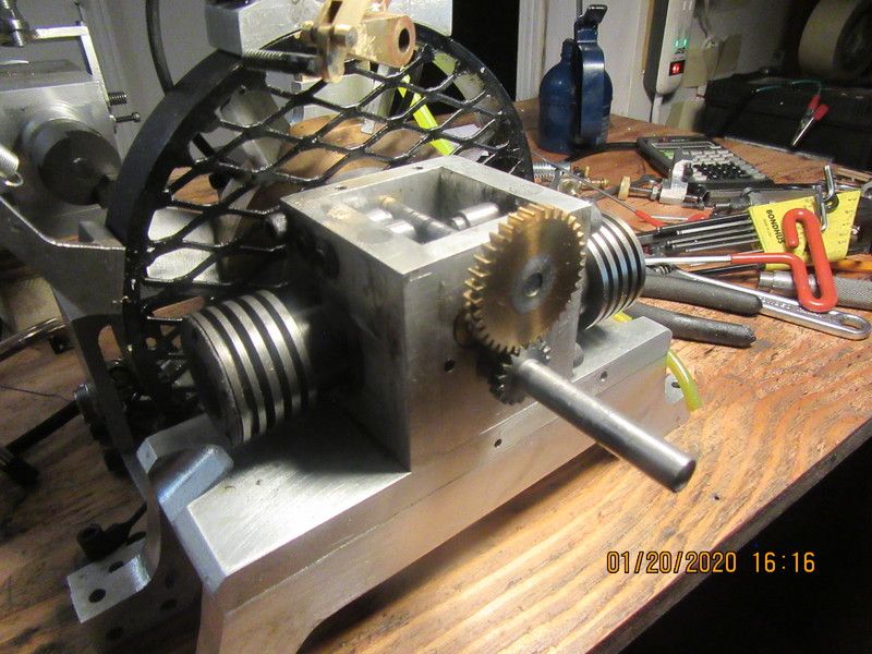
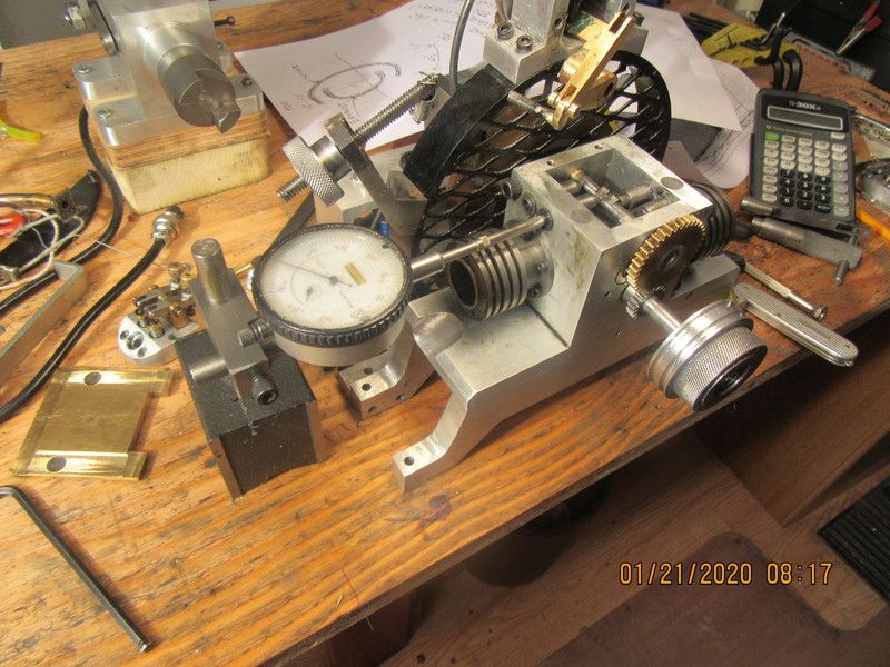
An update---I have hit the wall on this engine, for the moment. I have replaced gaskets, set and reset valve and ignition timing, replaced rings, replaced carburetors, and tested every individual part. Every member of the choir sings perfectly, but I can not get them to sing in harmony. This doesn't happen to me very often. I can't even get it to run with all of the self throttling apparatus disconnected. I haven't been able to identify anything specifically wrong with the engine, other than the fact that one valve adjuster was out by a fair bit, but even with that valve clearance readjusted, it refuses to run. When I turn the engine over by hand with the cylinder heads removed, it will put a good suction on my thumb which doesn't fade away, and gives a distinct "pop" when my thumb is removed. The gas lines are clear, and fuel will run from the hose when I remove it from the carburetor. The vent hole in the gas cap is clear. I have adequate spark at both plugs. engine spins freely with heads removed--no hard spots. Only thing left to do is remove the ignition points, starter hub, and brass gear cover so I can have a good look at the timing gears. Thank you for your patience.---Brian
 
This is one of those one of those "unexplained mysteries" that you read about in the National Enquirer. I've got the poor old girl stripped right down to her undies now, having just removed the starter hub, ignition points, and brass gear cover. One of the things that I just discovered which doesn't affect the engine (I don't think)---I pulled up the detail drawings of both gears to see what I used to hold them to the crankshaft and camshaft---and found nothing!!!--I never added the set screws to the detail drawings back when I originally built this engine. This is a bit strange, since I've sold half a dozen plan sets for this engine, and I have never had a call nor email asking about it. Next step will be to ensure the valve timing (valve beginning to open X number of degrees before tdc or bdc depending on which valve we're talking about). My software can let me set things exactly where they should be, degree wise, and then give me a linear distance from the top of the piston to the top of the cylinder. It doesn't appear that either gear has slipped from it's appropriate position relative to the shaft it sets on, but I will check it anyways. This is about as close to the "beginning" that you can get when doing engine forensics.
 
I have everything torn down to the bare essentials. I'm checking valve timing as we speak. Ignition cam is off the engine right now. Will reset everything as I build the engine back up.
SNiaPq.jpg
 
This set-up lets me know exactly when the cam lobe begins to contact the lifter. I rotate the crankshaft slowly by hand in the direction it normally turns, and as soon as the cam contacts the lifter, the needle on the dial indicator moves. At this point, I measure from the top of the cylinder down to the top of the piston. My software tells me that when the piston is 0.263" from the top of the cylinder, the rotational aspect aspect of 15 degrees before top dead center has been reached. Since I am leaving approximately .010" of valve lash, that figure will closer to 2.53" before the valve begins to move. Checking the actual distance with my Vernier caliper I measure .280" This is well within the range of acceptable, but since I have everything apart I will loosen of the cam gear and reset it to exact numbers. All of the cam lobes are 'fixed" to the camshaft, so any change I make now will affect al of the valves in the system.
vq7KDz.jpg
 
Okay--Something is a little hinky. Based on the intake valve having a lead of 15 degrees before tdc, the dimension from top of cylinder down to top of piston should be 0.253" which includes the valve lash of about 0.010". I have reset the left side of the engine to agree with this,(It wasn't very far out) and that automatically sets the right bank the same. However, the exhaust valves should have a 40 degree lead before bdc, which gives a dimension from top of cylinder down to top of piston of 0.894". I measure 0.710" which means a lead of 60 degrees which is 20 degrees too much. All of the four cam lobes are Loctited to the camshaft, which is an acceptable method of cam building. I now have to check the cams to generate real numbers instead of working with theoretical numbers and see what's going on.
 
The theoretical cam has 120 degrees of movement in the area which lifts the tappet. This translates to 240 degrees of crankshaft movement because of the 2:1 ratio between the crankshaft and camshaft. 240-180=60 degrees of movement which gets split between valve lead and valve lag. Theoretical split is 15 degrees before tdc. and 45 degrees after tdc. Real cam as measured with dial indicator has 130 degrees of movement affecting the tappets. This translates to 260 degrees at the crankshaft. 260-180=80 degrees to be split between lead and lag. 80 -15 degree lead=65 degrees of lag. 65 degrees of lag translates to measurement from top of cylinder down to top of piston of .706" and actual measurement on engine e is 0.710". This tells me that cams have not slipped rotationally on the camshaft.
oTqOim.jpg
 
Tonight everything is back together. Ignition timing has been reset, Cylinders have again been pressure tested, and gaskets are all in place, nothing leaking that I can see. Liquid dish soap has been flowed around the cylinder heads while under pressure, and we have no bubbles to contend with, which pretty well assures no leaking head gaskets. Valve lash has again been adjusted. While I had the intake manifold off I gave it the old "Blow your guts out test" just to make sure there wasn't a big blob of gunk in one of the legs blocking the flow. Did I really see anything that would have prevented the engine from firing or running?--No, not really. Tomorrow we will try to start this thing again.
 
Back
Top