Threading dial question

Home Model Engine Machinist Forum

Help Support Home Model Engine Machinist Forum:

This site may earn a commission from merchant affiliate links, including eBay, Amazon, and others.
Well I guess I made a mistake. When I said I was sucessful at doing 8 tpi with the threading dial I had only done 2 passes and it looked like each pass was aligned. I had to leave after that and in my mind I thought I had it all sorted out. Last night I went to finish the job and iafter a few more passes I started to notice that all was not right. It seemed that the thread was gradually moving to the left a little on each pass. When I came to notice this I stopped to think for a minute - is it really out or are my eyes just getting worse. Then I thought I' do a couple more passes. I waited for the "1" to come up on the dial and engaged the dial and then engaged the half nuts. On this pass the cut was no where near the right place. What am I doing wrong I thought. I couldn't figure it out so I went to bed and slept on it.

Today is a new day and I think I understand what went wrong.


Several month ago I was doing some threading without using the threading dial. I do not remember what pitch I was doing as it was not for anything important - I was just trying to teach myself how to do threading on the lathe. The threads wer cominig out slightly off (the pitch was not quite right). I checked the gears that I had installed and they wer right acording to the chart that is printed on the lathe. Here is the chart:

Threadchart1.jpg


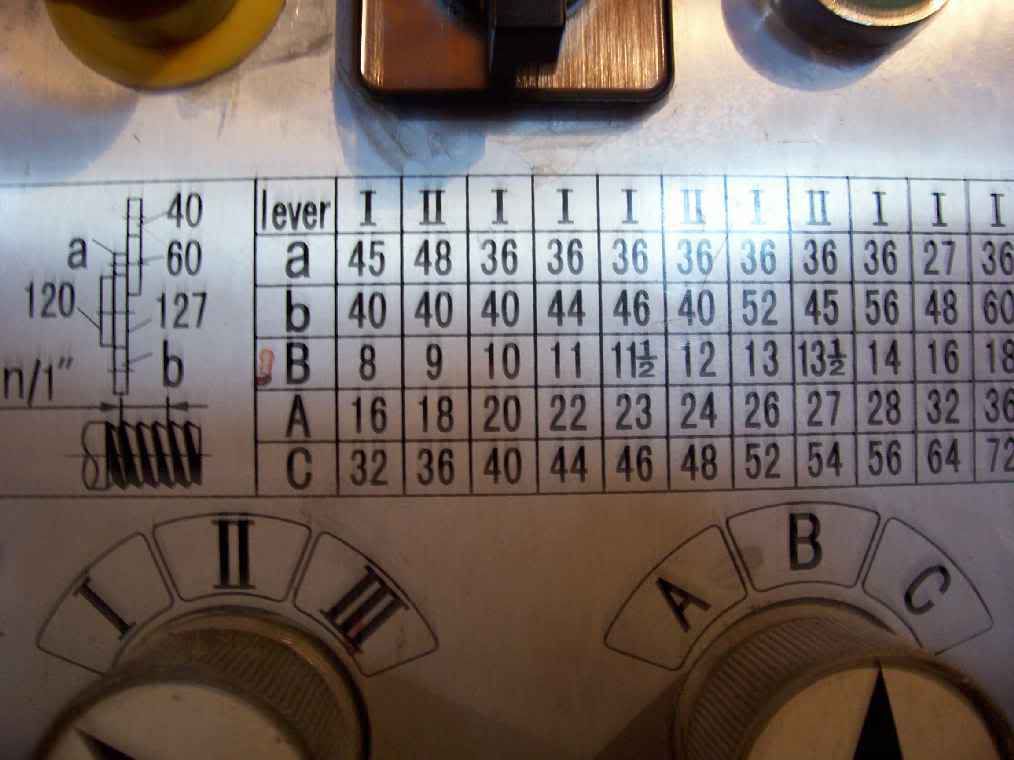
It took a couple of days playing around with it and thinking before I decided to calculate what pitch I should get using the gears I had set up. I didn't do this at first because I thought that was what the table was for. To my suprise the table was not correct It was full of aproximations. So I wrote a little program to calculate all the possible pitches I cut cut with the gears that I have - it even ruled out combinations that would not fit for one reason or another. It created a text file and sorted it by pitch so now when I want to cut a thread I just look in that file and find the pitch I want and use the gears that were calculated.


So when I set up to do 8 tpi I looked up in the table - the closest thing there was 7.988166 tpi. I thought that was close enough and it would be if I wasn't using a threading dial. I was cutting about 1 inch of threads so on each pass I was comming up short by .002 inches. This can easily be missed on the first 2 passes by a rank amature like me. It also explains why the last cut was so bad. As I stood there thinking about what could be going wrong the lathe was still turning and the spindle was getting more and more out of sync with the leadscrew. So anyway it looks like I can not use the threading dial for 8 tpi on this machine or 9 tpi or 10 tpi or 11 or 11.5 or 13.5 or 14 or 16.

As an example of how bad the table is on the lathe look at this.

The table says for 8 tpi use the gears 40/60 45/120 127/40 and put levers in B and I.

(40/60) X (45/120) X (127/40) = .79375

Levers in B I multiplys this by 2

this gives 1.5875

divide by 12 (lead screw tpi) gives .13229166

the recprical of this gives the threads per inch = 7.559.

7.559 is a long way off of 8.

My program calculated the closest possible set of gears to be 40/60 52/120 127/44 with levers in B and I.

this gives 7.988166 tpi - much closer but still impossible with a threading dial.


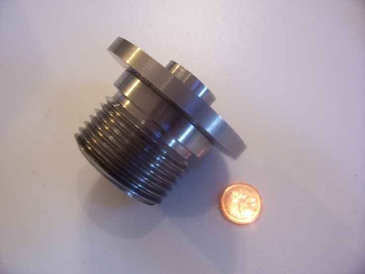
The thread I want to make is to a shoulder so it is going to be difficult without using the threading dial.
 
I uploaded the new chart that I made for threading on the C6. If you happen to own a C6 AKA Grizzly 0602 you should download this file. The table on the lathe is really bad and should be painted over. The file is just a text file and it gives the gears for imperial and metric threads.
 
I don't know anything about your Grizzly 06 but when cutting threads, you usually advance the cutting tool with the compound set at 30° (some prefer 29.5°) so that the tool advances in and to the left at the same time. With this method, you are only cutting with the left edge of the tool and the crest of the thread is moving to the left with each advance of the compound.
 
More confusion.

Look at the picture on your chart. According to it, 40 meshes with 60, then "a" meshes with "b" - the 127 is used only as an idler so doesn't figure into the final answer.

Thus...

(40/60) * (45/40) = 45/60 = 3/4

(3/4) * 2 = 3/8

(3/8) * (1/12) = 1/8

Take the reciprocal and you've got 8 tpi.

I'm not questioning that your threads are coming out wrong but I do think you need to check your calculations and understanding. For instance, you include the "120" gear in your calculations and, according to the diagram, it isn't in the indicated gear train. [It's probably used when cutting metric threads.]

Just as a sanity check (mine, not yours) let's try for 10 tpi. We have:

(40/60) * (36/40) = 36/60 = 6/10

(12/10) * (1/12) = 1/10

and the reciprocal is, yup, 10 tpi.
 
Thanks mklotz for taking the time to read the details and figure this thing out fore me
Now another light has come on.

I was looking at the diagram wrong. I thought the 120 tooth gear meshed with b, after all why would the 120 tooth gear be there if it doesn't mesh with anything. I guess it is just used as a spacer. I wish I had of read your post before I spent all afternoon yesterday using the wrong set up. But in the end I learned something.


Finished1.jpg


This is what i managed to make yester day. I used the gears setup to make 7.988 TPI since I didn't know how to set up for 8.000 TPI. The procedure I used to turn to the sholder I used was as follows.

With the carrage to the right and the half nuts disengaged I turned the spindle until the number 1 was indicated on the threading dial then stoped the carrage and engaged the half nuts. Also zero the cross slide dial. Now I am set up and will repeat the following steps.

1) Use the compound slide to set the depth of cut.
2) Turn motor on with the half nuts engaged and let tool cut as carrage moves to the left.
3) When the carrage gets to the thread relief area disengage the half nuts and then turn off the motor.
4) Use the cross slide to bring the tool out of the threads.
5) Run the motor in reverse and engage the half nuts when the dial gets to 1
6) Let the carrage go to the right untill it is in the same place as it was when you started in step 1
7) Dial the cross slide back in to 0
8] Go back to 1 and 'repeat till done.

It worked perfect and should work for making threads of metric pitch on an imperal lathe.

 
Smoggy,

Now that we've established that the lathe gear chart is indeed correct and the chart you uploaded is based on erroneous observation, you may want to think about asking one of the administrators to remove the upload so it doesn't cause confusion in the future.

Your latest procedure for thread cutting looks ok except for the fact that, by always engaging on the same number, you're not using the threading dial the way it was intended to be used. I strongly encourage you to try the experiment I've already described. On a piece of scrap, set up for 18 tpi and then try tracing the threads while reengaging at 1,4,7,10 on the dial.
 
mklotz said:
Smoggy,

Now that we've established that the lathe gear chart is indeed correct and the chart you uploaded is based on erroneous observation, you may want to think about asking one of the administrators to remove the upload so it doesn't cause confusion in the future.

Actually the chart I uploaded is correct. It uses a different setup in the gear train than is shown on the diagram in my picture. On the picture the 120 tooth gear does not mesh with anything. In the table that I uploaded the b gear would mesh with the 120 tooth gear rather than the 127 tooth gear. So the table that I uploaded gives thousands of other possible spindle to leadscrew ratios shuch as the one that I used that resulted in 7.988 TPI. It may not have any be practial use but it is correct.

 
mklotz said:
Smoggy,

Your latest procedure for thread cutting looks ok except for the fact that, by always engaging on the same number, you're not using the threading dial the way it was intended to be used. I strongly encourage you to try the experiment I've already described. On a piece of scrap, set up for 18 tpi and then try tracing the threads while reengaging at 1,4,7,10 on the dial.

The threading procedure that I posted was for threading to a sholder when using pitches that don't divide into the leadscrew pitch for example 7.988 TPI. When I made my part I had the gears set up for 7.988 TPI which makes it impossible to use the threading dial the way it was intended to use. I thought I would post the procedure because it gives a way to thread to a sholder when doing metric threads on an imperial lathe. Anything I have read on the net says that you need to leave the half nuts engaged all the time when doing this - but you don't as I have just shown.

Now that I now how to set up the gears the way they were ment to be set up, I will be trying to use the dial the way you explained. I can't believe how long I have been confused about all this but now it is all perfectly clear. I would have been a long long time figuring this out with out your help - so thanks again.
 
I have updated my program. It now generates all the combinations that were missing from the first program. It now gives all the combos that are listed on the lathe plus more. The complete list results in 9,018 combinations (counting the gearbox settings). This rtesults in 3,370 different spindle to lead screw ratios. Now if someone could explain how to replace a file in the upload section I would go ahead and do that.
 
Hi all,

Just about to try some screw cutting as I need some 1/4" x 32 bungs for a model loco boiler that needs hydraulic test and don't have taps or dies!

Got another question, applogies if it's been covered. Why put the compound slide at 29.5 degrees? I've heard it's so there is only load on one face of the cutter or something? Don't get it. Also, why 29.5, why not 30?!

Cheers,

Nick
 
Still don't understand this putting the top slide over stuff, someone will need to get crap-o-cad out to show me I think!
 
Threadingangle.jpg


The diagram on the left shows what happens when the cutting by going straight in. As you can see the tool is cutting the same amount on both sides of the cutter on each pass. The diagram on the right show what happens when you advance the cutter using the compound at an angle. The angle the diagram is exagerated to make the effect stand out better. At 29.5 degrees the tool is cutting almost entirely on the left side of cutter. On the final pass the tool needs to be advanced straight in to remove the zig zag left on the right hand side of the cut.

 
Thanks for the diagram but I still don't understand why that is necessary. The way I thought to cut the thread was to put on my cut further along where there is no material then let the saddle go into it, rather than plunge into the work piece with it all running?
 
NickG said:
Thanks for the diagram but I still don't understand why that is necessary.

I don't think it is necessary. It is just easier on the machine and requires less power to go the same depth. Threading on small bench top lathes can push the machine to it's limit in very small depths of cuts, so to complete a thread will take alot of passes and therefore alot of time. Advancing the cutter on an angle will alow you to go deeper on each pass so in the end the it is faster. Of coarse I am no expert on the subject as I have only have about a total of 4 hours of experience in actual threading with about 3 hours and 50 minutes of total screw ups. I am only giving you my interpretation of what I have read about it and what I have learned in that short time of trying it myself.
 
NickG: In the beginning (Noah's lathe) there was no compound on lathes and threading was done straight in. As Smoggy pointed out, on a coarse thread, when you get in deep, there is a high load on the lathe and you quickly develop chatter.

If you have enough rigidity and horsepower there is no reason not to go straight in but if you try it both ways, I think you will find the compound advance easier to do. Back out at the end of the thread with the cross slide handwheel, move the carriage to the other end, return the cross slide to your zero and then advance the cutter with the compound.

Thanks for the diagram but I still don't understand why that is necessary. The way I thought to cut the thread was to put on my cut further along where there is no material then let the saddle go into it, rather than plunge into the work piece with it all running?

I'm not sure what you mean by this, but the correct procedure is to advance the cutter with the cutter away from the workpiece thread before you engage the half nuts.
 
At work I've cut threads that were 2" pitch and 1-1/32" deep.
To cut them the tool was obviously advanced on a 29.5 degree angle.
Even at that it was a battle with chatter.

For a hobby scale thread, even up to a 1"-8 pitch, straight in will cut just fine.
People will be lining up to tell you how wrong that is.
All I can say is it's worked fine for me for the past 20 years.

When you start into a 2" pitch thread and see a 9" boring ram flex under the tool
pressure but the thread still ends up being perfect, you kind of loose your fear of
going straight in on a small thread.

Rick


rake60: I defer to you knowledge and experience cutting threads straight in but I have had trouble cutting 1 1/2 x 8 inside threads on a 9" Southbend even when advancing the compound. When the biggest boring bar the lathe will hold is 1/2" the bottom of that 8 TPI thread is tough to do without chatter.

I am sure the professional machinists can do it, and probably do it all day every day, but for the amateur model maker who does it once a month, it is tough.
 

Latest posts

Back
Top