- Joined
- May 18, 2010
- Messages
- 84
- Reaction score
- 10
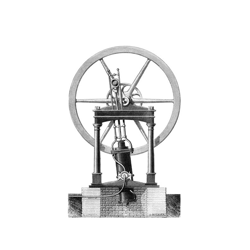
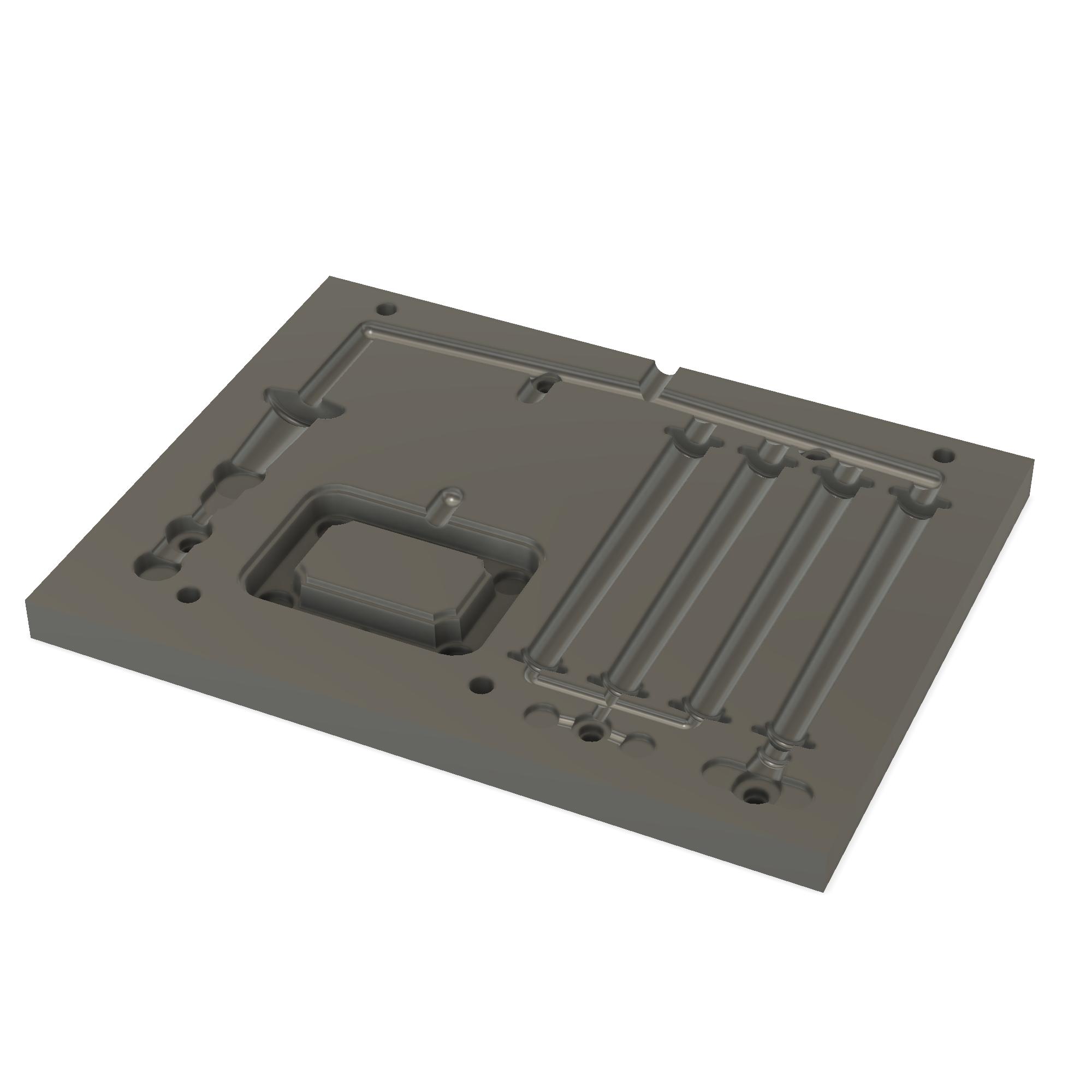
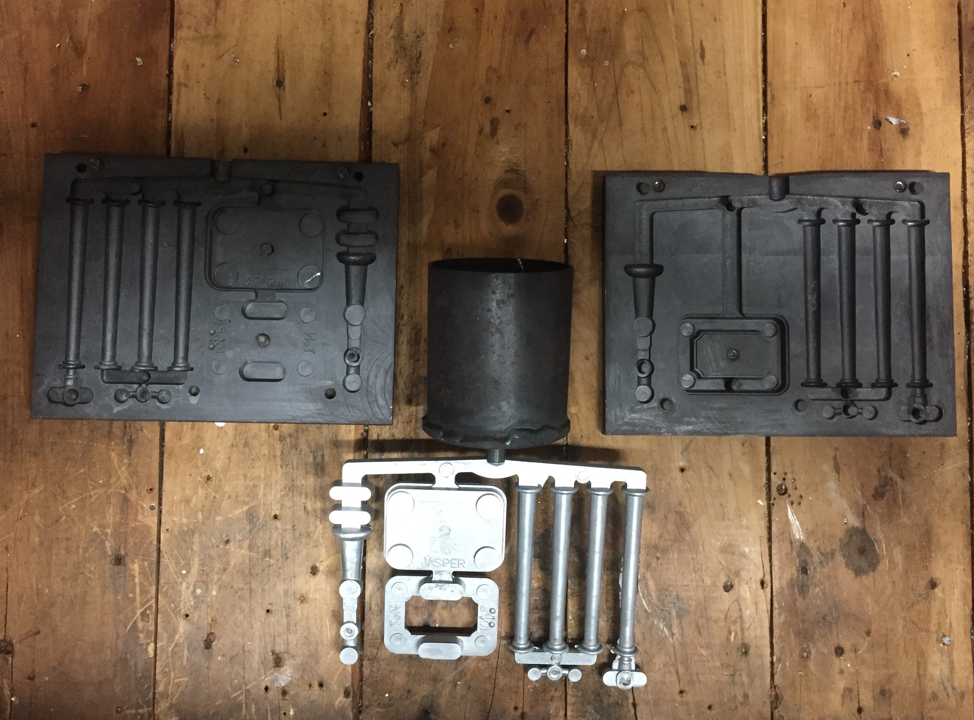
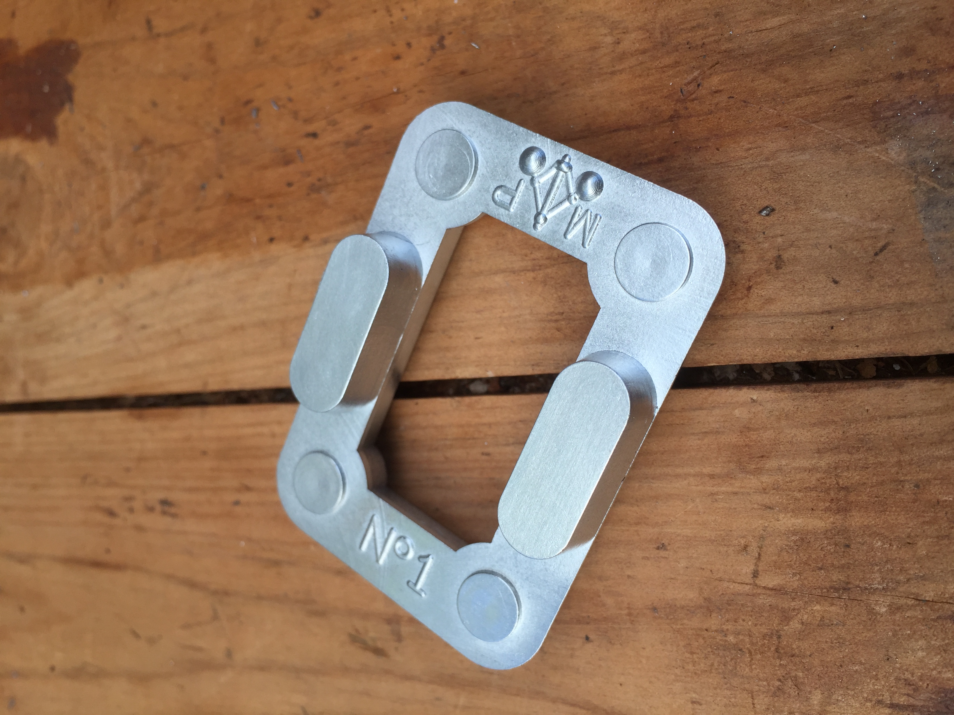
Welcome to the build of Jasper, a double-acting oscillating steam engine incorporating a sun & planet gear. I'm aiming to share the highlights of this build rather than a comprehensive build thread, as I simply forget to take enough photos for the latter. To begin, here is a brief clip of the 3D model I've drawn up in Fusion 360, along with an illustration by Albert Jahandier from a book published in 1876, which I've used as inspiration for the build. Thanks for watching.