The French horizontal mill with slide valve drawn up by JD Waal in New Zealand

Home Model Engine Machinist Forum

Help Support Home Model Engine Machinist Forum:

This site may earn a commission from merchant affiliate links, including eBay, Amazon, and others.
Jason is correct, JB Weld is a friend to any modeler. It is now available in a High Heat formula that I am dying to try out. He is also correct in assembling the pieces and then performing the traditional diagonal drilling operations in order to achieve the port induction is a tried and true standard. Even simply employing the "harder" soft solders will stand up to the low pressures involved in this example.

Are you saying that JB weld is BETTER than silver solder? Im sure it is easier to apply but will it last and will it hold under 30-40 lbs of steam?
 
I have been redrawing this so I can more easily understand what this engine is and I have come across a problem: There is a section that says such and such is in assembly dwg "106" but there is no 106. This assembly is with the cylinder and a special valve base which fits into the side groove of the cylinder. Well, there is no method of attaching the two and holding them so I assume they are silver soldered. I have very little silver soldering experience and as tiny as the part is, it looks like a bear. i have been reading the forum comments about silver soldering and that helps a bit. I will send a jpeg when I can get it converted from bmp.
The way I silver solder small parts is quite simple... First get some silver solder and a fine file and file the silver solder and catch the filings of the solder make sure that they are collected clean and when you have enough for the job at hand mix the fine filings with the solder flux and the carefully apply evenly to the surface of one of the peace's to be soldered an fit together clamp together and then heat and watch the solder run silver line at the edge of the join. Let cool and job done. Quick and simple and you have no solder in the wrong area Hope this helps and practice on a couple of brass or bronze pieces to get the feel for it. John
 
JBWeld works for those that can't or don't want to solder. Probably better than a poor silver soldered joint and better if you want to make your fabrication from cast iron which although it can be silver soldered is not easy to do so.

The High temperature one has always been the one to use as it is much stronger and obviously takes the heat of the steam better, this is sold as the "Original cold weld Formula" in red and black tubes. Don't be tempted by the rapid or marine versions.

Myself I'm a flux and feed in the rod man when it comes to silver soldering. On this engine if you want to save a bit of cash then use hollow bronze stock for the actual cylinder and separate flanges that slip onto a spigot turned on each end of the cylinder for location. Leave all machined surfaces over size so you can do final machining after solder/bonding.

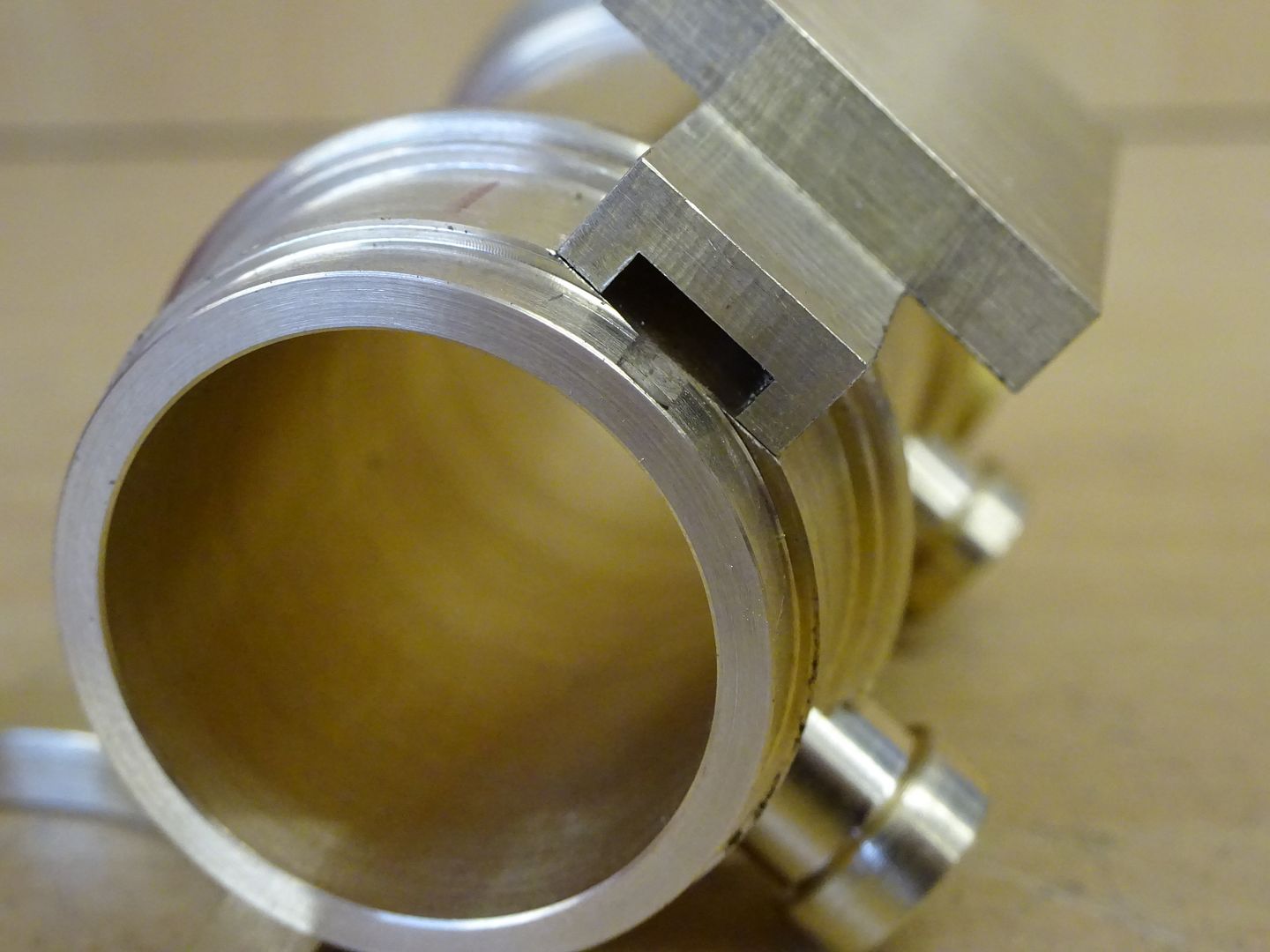
DSC01731_zpslxn2ujl9.jpg


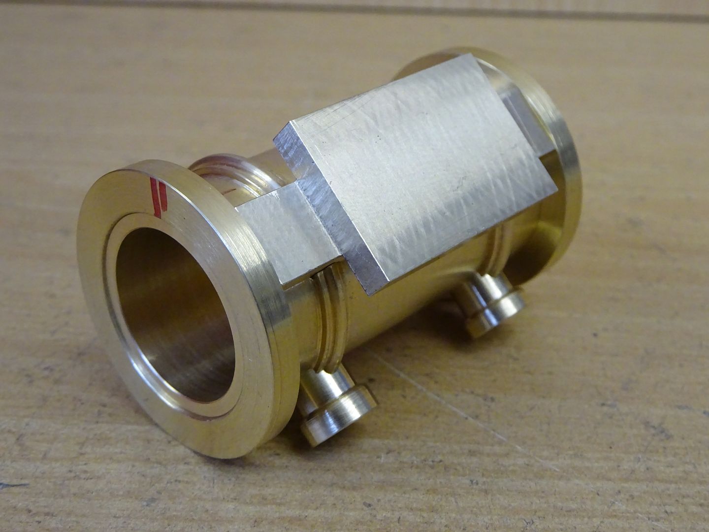
Photo_8.JPG


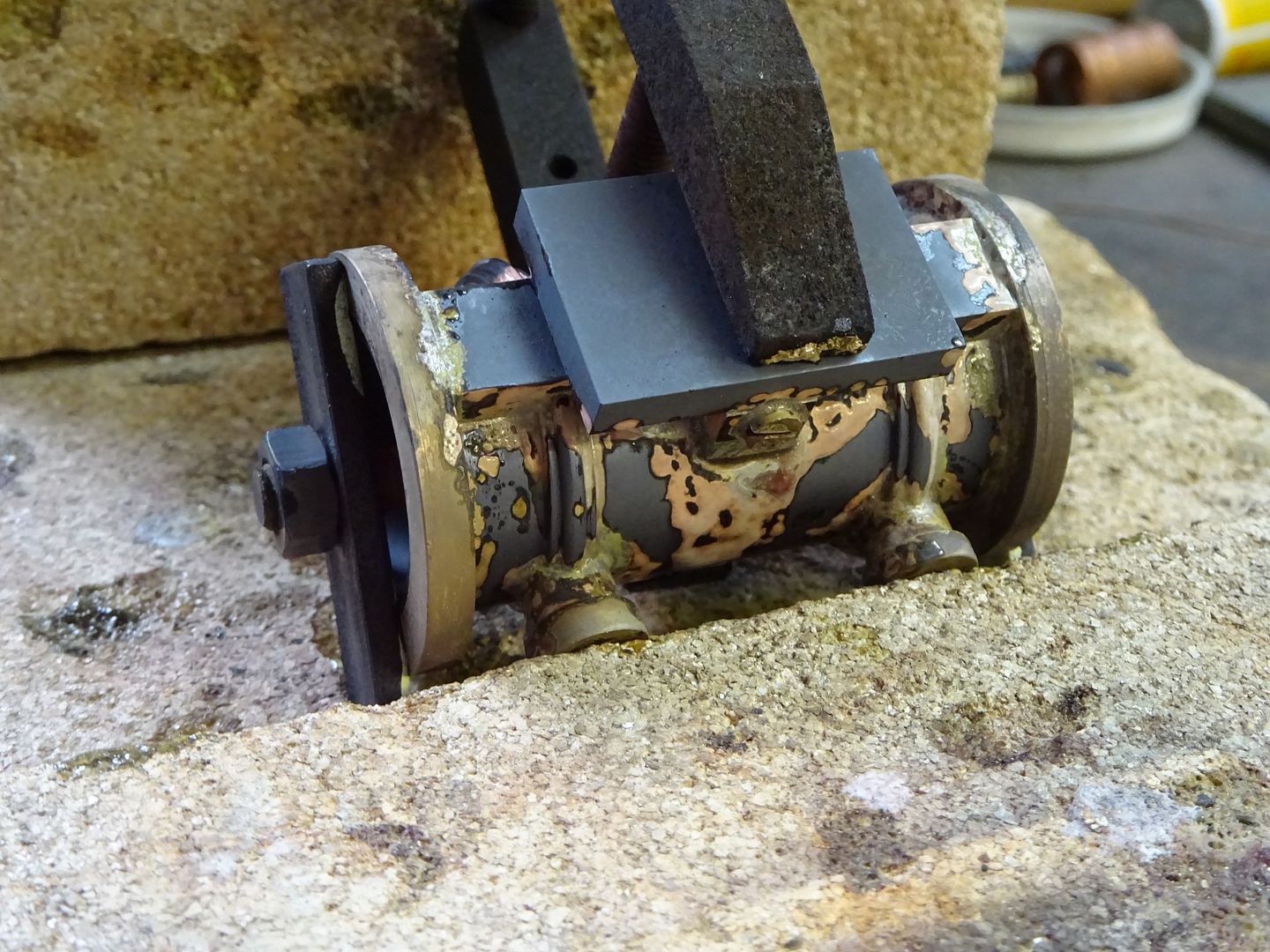
DSC01732_zpsrsft6zdw.jpg


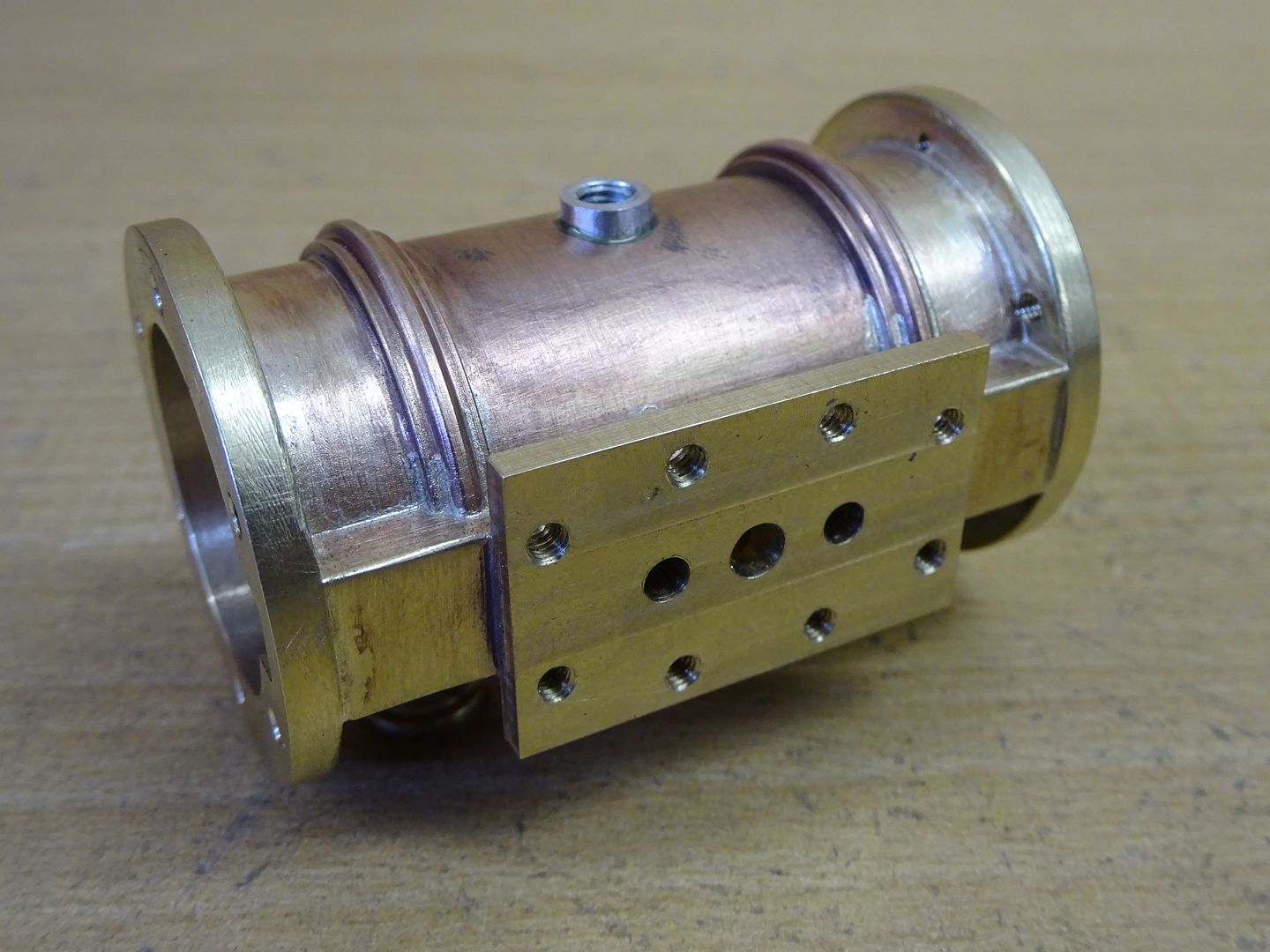
DSC01740_zpsbu9ntmdo.jpg
 
I'm presently redrawing for my own use, a De Waal drawing. I have found, however, something I cannot understand. The project is 09A-15-00 (2014)--the 4 cylinder boxer type single oscillator. There are four copper tubes, two from the first steam chest which he calls "port block" going to the second block. That looks fine, however, there are two input copper tubes also. All four of these seem to be inserted in the first block from underneath, however, there are only three holes for them. Does anybody understand what is going on? I must be blind or made some silly mistake but I can't fathom it. Also, the rocking valve has a little handle on it but there doesn't seem to be a mechanism to rock it. What am I not seeing?
 
There are 4 holes in the bottom of the block, three in a line and one offset, look closely at the exploaded 3D view and you can see the far pipe is not in line with the others, this shows up even more on the side view of the assembled engine.

The "rocking valve" is actually a reversing valve that YOU move to alter the direction of rotation.
Oh, Thor and Wotan, how could I have misst that fourth hole? That's really something. Thanx for pointing that out. And thanx for letting me know about the reversing lever. My worst daymare would have been trying to follow the steam path in order to figure out what was happening. There is another engine that has a valve just like that but it's function is like a slide valve which alternately feeds a double acting piston. This one's pistons are single acting, however I thot the "rocker" must have fed left and right pistons some how. As there are four pistons, it would have been hell following the steam .
 
Oscillating engines do not have separate valves, the movement of the cylinder's flat face over the port face acts as the "valve" whether single or double acting.

Have you built any engines before? may be worth doing a simple single cylinder oscillator first to get a feel for how things work.
 
Oscillating engines do not have separate valves, the movement of the cylinder's flat face over the port face acts as the "valve" whether single or double acting.

Have you built any engines before? may be worth doing a simple single cylinder oscillator first to get a feel for how things work.
No, have not done any yet. Drawing them up is the first part for me. You can see how ignorant I was on this one. The original drawings are very confusing. And yes, I intend to make one. This four cylinder seems to be an easy build once I get the drawings right. Thanx for the pointers.
 
The way I silver solder small parts is quite simple... First get some silver solder and a fine file and file the silver solder and catch the filings of the solder make sure that they are collected clean and when you have enough for the job at hand mix the fine filings with the solder flux and the carefully apply evenly to the surface of one of the peace's to be soldered an fit together clamp together and then heat and watch the solder run silver line at the edge of the join. Let cool and job done. Quick and simple and you have no solder in the wrong area Hope this helps and practice on a couple of brass or bronze pieces to get the feel for it. John


Now, that makes sense! Most of what I want to solder is little stuff (like my Jenny Wren), and somehow it's hard to find any silver solder less than 1/8" in diameter, so just feeding that in is both messy and wasteful.

Thanks for the "soldering tip". 😉
 
Are we starting to talk about two different solders here? The mention of a silver line and not being able to get below 1/8" dia would seem to indicate soft plumbers solder, not hard holder or braze as some know Silver Solder as. Particularly if used with steam then a solder that melts at 640deg C is the type to use and what is shown in my photos.

As for filing your own both soft solder and silver solder pastes are available.
 
Now, that makes sense! Most of what I want to solder is little stuff (like my Jenny Wren), and somehow it's hard to find any silver solder less than 1/8" in diameter, so just feeding that in is both messy and wasteful.

Thanks for the "soldering tip". 😉
My son bought the silver solder we use. It is tiny, I thimk it is less than 1/16th. Don't know where he got it, on line I suppose.
 
Are we starting to talk about two different solders here? The mention of a silver line and not being able to get below 1/8" dia would seem to indicate soft plumbers solder, not hard holder or braze as some know Silver Solder as. Particularly if used with steam then a solder that melts at 640deg C is the type to use and what is shown in my photos.

As for filing your own both soft solder and silver solder pastes are available.

It seems that very small-diameter silver solder is more readily available in the UK than in North America, but shipping costs are very high, especially if you buy from eBay with its Global Shipping Program. The 1/8" silver solder I have (and it is cadmium-free 50% silver, NOT soft solder) is meant for brazing copper tube used in refrigeration, etc.. That is what I intend to file down, and for me there's no sense buying the paste when I have 50 Troy ounces of silver solder lying around.

Don't know about a "silver line;" that's from someone else's post.
 
Back in the day, I did an awful lot of brazing, I've done a lot of electronics soldering, some copper plumbing and a little silver soldering. I also have a friend who braze-repairs faulty bronze castings. Its my understanding that when brazing iron or steel, the choice of stick alloy depends in part on the desired local alloy effect. I was told the braze joint is actually stronger than the surrounding steel - if done well. And you can braze cast iron (but you can't weld it) - handy for broken castings. I once brazed a broken pot belly stove.
As far as silver solder is concerned, if you want the good stuff I'd look at jewelers supplies, and it is silver so it will be expensive! I wouldn't trust 1/16th. I don't know about the metallurgy of plumbers solder on copper, but its basically just molten lead glue (which proper silver soldering isn't.)
As usual, clean surfaces and the right flux in the right places in the right amounts. We used to mix the powder flux into a water based paste, paint it on joints before assembly, clamp together, let dry, and wipe off external flux. The braze - or silver solder, will only flow where the flux is, and when it is at temperature. Neophytes think you heat to solder or braze rod. You don't. You heat the parent metal until the solder melts on contact.
 
Back
Top