TB2 - Elmer's Coomber #46

Home Model Engine Machinist Forum

Help Support Home Model Engine Machinist Forum:

This site may earn a commission from merchant affiliate links, including eBay, Amazon, and others.

Flywheel Material??

  • Brass

  • Aluminum

  • Steel

  • Other


Results are only viewable after voting.
Well, I decided to see if I could figure out this crazy cam ring. It took me a bit to get my head around it and figure out how to draw it. But I think everything turned out OK? I printed it out and scanned the image. Here it is. From this I have a piece of aluminum plate that I can make one of these 3X bigger:eek:)

Coomberscamring_edited-1.jpg


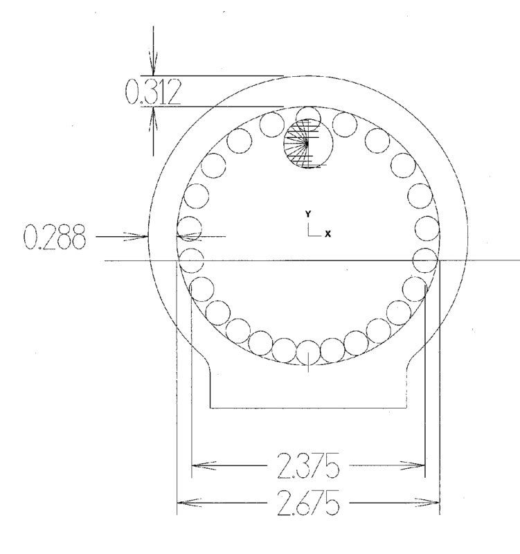
I just have to scale it up and do a toolpath on it. I drew it up with Mastercam. The hard part was the line that the rollers roll on. I had a heck of a time getting it tangent with the rollers.

Later, Wes
 
Dick L. said:
Ok, I checked and I have 2" Brass for 16 flywheels I'll donate to the build if that's the way we go. It's made up of end cuts but the OD isn't marred up much.
Dick

I believe we are going to go with brass ;D

Eric
 
Thicker base sounds good. Regarding the flywheel ,if we move it outside we could extend the hub slightly for a set screw to eliminate the threaded hole in the rim. Might need to extend the shaft slightly as well. We will also need a collar to keep the load off the forks and cam. Has anyone ever done a flywheel with different metals, like a brass hub and stainless rim pressed or shrunk on?
Dick
 
On the small end bearing we could use a flanged oilite bushing to carry the thrust and load better. I expect it's light but less drag is better right ?

Dick
 
bretk said:
Agree on the thicker base, I would also like to propose moving the flywheel outside of the second support, thus making it easier to see the piston movement and allow the flywheel and cam ring not to appear so cluttered and close. What does everyone think?

-Bret

I wonder how hard that would be? And will it effect the performance of this engine?
 
If the flywheel is moved outside the bearing, then the bearing can be moved closer to the cam.
I was thinking about making the shaft an add-on instead of removing a whole lot of brass. Moving the flywheel out and the bearing in a bit will allow more meat on the cylinder for a stronger mating of the shaft. Maybe even a larger diameter, like 1/4 inch instead of 3/16?

Any thoughts on the add-on shaft?
 
Looks like this may turn into a design build after all. I high suggest we work up some drawings with all the changes so everyone makes parts to fit and to the same design.
Tim
 
zeusrekning said:
Looks like this may turn into a design build after all. I high suggest we work up some drawings with all the changes so everyone makes parts to fit and to the same design.
Tim

Hmmm.

I don't want it to turn into a design build. I think that will come a little later. At this point, I would like to see the modifications only be cosmetic or simple. I think at this point we should leave the flywheel where it is.

Give me a little bit of time to get the Team Design going and it will be intersting. Sound good?

Eric
 
Eric,

As far as the flywheel thing goes, can we just make the shaft a little longer and let people put it where they want, I don't think its that big a deal.

As far as moving the support in and using a setscrew on a hub as opposed to having a hole in the flywheel rim, well yes that would be a design change, but not a big one?

-Bret
 
I have been looking over the plans...

Is it me or does the flywheel help keep the rotating cylinder in place by not allowing it to slide out?

Eric
 
I think the roller forks do that? To bad this engine can't be taken apart after it's done. The forks are soldered to the shaft:eek:(

Wes
 
Kevin,
On the one I built, I drilled and reamed a hole through the cylinder/valve for the shaft and soft soldered a length of 3/16 12L14 in. The shaft was center drilled before soldering in. Then I turned the valve and faced the cylinder with the one end of the shaft in a collet and supported by the center in the other end. Milled the sides and ends and then drilled and reamed the bore after putting in the steam passages. there was no problem going through the 12L14 in the middle of the cylinder as it cuts much the same as brass. If that was a concern you could use a 3/16 brass rod for the shaft. I also extended the shaft through the valve by about 3/8 inch so I could put the flywheel on the back side of the engine so I could see the cylinder action. The flywheel helps it run slower, but if you watched the video of mine you saw that it runs fine with out a flywheel. (I had "borrowed" the flywheel)

Dick,
I put a brass bushing in my outboard support. I have noticed that there is some wear at that bearing, probably from the unbalanced mass moving about as the piston moves. It can't be balanced as things move about. I think a oilite bushing would be a good idea. They are cheap and easy to obtain.

Gail
 
Yes Eric , that is why I said we need a collar if we move the flywheel outside the bearing. Without it the forks will rub on the cam ring and cause excessive drag for sure as well as the cylinder floating out of it's valve alignment.
We could still get a tapped hole in the hub with the flywheel inside but it will need to be on an angle with a brass pellet under the set screw to distribute the forceand not burr up the shaft.

Dick
 
It sounds like all we have to do is make the shaft a bit longer then? That should be fine. Then the owners can decide which side of the bearing to run their flywheel. Also would leave extra to run an accessory with:eek:)

Wes
 
Eric,

If you look at the video of it running, he doesn't even have a flywheel on it.

-bret
 
I had a question Bretk. Will it run slow with the flywheel? Just wondering:eek:)

Wes
 
Powder keg said:
It sounds like all we have to do is make the shaft a bit longer then? That should be fine. Then the owners can decide which side of the bearing to run their flywheel. Also would leave extra to run an accessory with:eek:)

Wes

I agree ,I would leave the bearing where it is so we don't have extra holes in the base. Flywheel size won't change. Location would be up to the assembler. :D We would need to add the collar though in the event the flywheel is used outside the bearing.

Dick
 
Powder keg said:
It sounds like all we have to do is make the shaft a bit longer then? That should be fine. Then the owners can decide which side of the bearing to run their flywheel. Also would leave extra to run an accessory with:eek:)

Wes

We'll have to change the print to add a second set of mounting holes for the alternate bearing position? Or is the idea just to add some sort of spacer and use the original location?

Joe

Dick: you answered this while I was typing! You're too fast or I'm too slow!
 
Wes,

Yes, the more mass, the more momentum to help smooth out the uneven power strokes inherant in a steam engine, the reasomn this engine runs without one is the cylinder acts as a sort of flywheel. I would hope it would run slower with more rotating mass.

-Bret
 
Ok... So we use Gails method and do the shaft longer. I say we leave the bearing mount points alone and design a collar.

Sound good?

Eric
 

Latest posts

Back
Top