Taper locks

Home Model Engine Machinist Forum

Help Support Home Model Engine Machinist Forum:

This site may earn a commission from merchant affiliate links, including eBay, Amazon, and others.

Parksy

Well-Known Member
Project of the Month Winner
Joined
Dec 9, 2015
Messages
327
Reaction score
349
Gday all

Can someone please explain or show me with some pictures the taper lock system used to secure flywheels to shafts. I have a vague idea on how they work, but I'm just curious what components need to be made and what locks into what.
I hope this makes sense

Thank you all

Andy
 
Thanks for posting that. I'm curious about how to make a half tapped hole though. Or is it a matter of making a full thread then removing material?

What angle is the taper for these things? What about bore angle? Is that all there is to it? A bore (such as a flywheel) then the bush inside it which is fastened to the flywheel and the taper which acts against the bush to hold it on the shaft?
 
Basically, I would suggest that the simple example in Sparey's The Amateurs Lathe is the one that I use. True, there are fancier gadgets but if one wants to hold a cylinder for say a second operation externally knocking up one out like he suggests with a hacksaw a drill and a tap and Allen bolt and you are away. Great- dead simple.

Hope this helps

Norman
 
Taperlocks

Using a jig for doing a taperlock bush yesterday and it struck me as possibly not many people appreciate the use of these items.
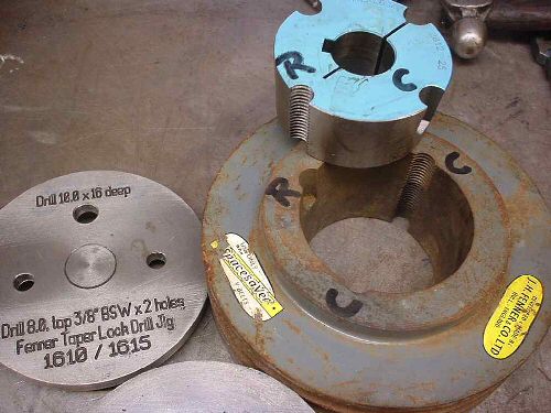
A pic of what I'm talking about.

fenner1.jpg


The bushes come in various ranges that denote the same outside dimensions and in that range you get various bore sizes.
The one in the picture covers the 1610 and 1615 bush series.
You can rebore and key to suit the application. I tend to keep some of the lowest sizes in stock for emergencies.

Forgive me if I'm teaching people to suck eggs but some won't have seen these and they are a life saver.
The bush is tapered and fits into a tapered hole in the gear or pulley. There are two 'nearly' opposite holes that are 1/2 holes running partway down the side, marked C on the bush. These mate up with two tapped holes running thru in the pulley, again marked as C.
The principle is you fit the bush to the pulley then onto the shaft and tighten the two allen grub screws supplied into the two holes marked C, these hit the bottom of the bush and force the taper bush into the pulley to lock the whole assembly very tightly together.

Opposite the two clapming holes is an extra hole marked R, this is the release hole and is machined opposite the the clamp holes i.e. blind hole in the pulley, threaded hole in the bush. To release the bush you remove both allen screws and replace one in the release hole, when it hits the bottom of the blind hole it jacks the bush out. Very neat, no pullers or hammers.

To use these in a pulley that has a parent bore or a normal bore that's been damaged you need to mark out the three holes on the pulley, drill one blind, drill two thru and tap and then machine the taper to give the 1/2 holes. The holes in each bush range are unique, no range has the same layout and they are never at 180 or 90 degrees to each other.
I managed to get the relevant information from Fenner, the inventors of this system, a few years ago and have made a series of jig plates up. I lay the plate on the pulley using an adaptor bush and spot the holes, drill and tap, then machine the taper.
All the tapers are 4 degree's per side, 8 degree's included.

If anyone wants I can supply the jig plate dimensions either as DWG or DXF files for the ranges that appeals most to the home shop.

These bushes are quite chaep, easily obtained and save having to wels up or resleeve damaged pulleys. It also possible to swap pullies between application just by changing the bush.

John S.
Nottingham, England.​
 
Please DO post the files, DXF/DWG/PDF (better, all three!)

These, and indeed the ones with flanges more commonly available in the US, are very useful. Being able to mix and match pulleys with various sized motor shafts makes changing motors much easier. The jackscrew arrangement for removal is extremely convenient as well.
 
I just make the male and female parts then drill two short clearance holes
and two long threaded holes. Or six if larger, three of each. Knock 'em
apart then rotate. Done!

Pete
 
I just make the male and female parts then drill two short clearance holes
and two long threaded holes. Or six if larger, three of each. Knock 'em
apart then rotate. Done!

Pete

Ok I understand this. I would like to give this a go. I just don't know how big a taper I need. A couple of degrees? i assume the bush and the bore taper have to differ slightly?
If the shaft is 10mm, what size bush should I aim for? I apologise if these questions seem repetitive.

Thank you all for your help. Your posts are very informative and helpful.

As John S. said in his post below, the tapers are 4* per side, 8* total. I'll take
a swing at your 10mm shaft, but without sketching it out so.....

I like stout screws so I'll go with 6-40s, two of them 180* apart. That means
you'll lay out 4 locations to drill. Two 180* apart deep and threaded, and two
90* from those drill shallow. Now if you're brave, or just good, with tapping
small holes you might go with 3 each 4-40 screw. I'm not good with those tiny
taps so I avoid them if I can. For 3 screws you lay out 6 places....

As for diameters, you only need enough 'wall' thickness, ID or OD to keep
all the screws in the parts. No breakouts allowed!;) And the screw holes
are drilled parallel to the bore, not the taper. And don't forget to split the bushing,
see the pic in John's post.

Let me know if that helps and if I can clear up anything. I think once you
try 'em, you'll like 'em!!

Pete
 
Thank you Pete. I did re read johns post after I posted and found my answer, feeling silly. Anyways, thanks again. I will re post after giving this a go. Looking forwards.

Cheers
 
Thank you Pete. I did re read johns post after I posted and found my answer, feeling silly. Anyways, thanks again. I will re post after giving this a go. Looking forwards.

Cheers

No worries Mate!! Here is a link to the Fenner site:

http://www.fennerdrives.com/

You will find all sorts of stuff there including their B-LOC keyless bushings. If you go to the Resources tab at the top of the page you will find
installation instructions for the various models. This is cool 'cause there are
section drawings of the units which might help you visualize the workings.

It's been my experience that just about anything I've seen in industry can
be scaled down for model use.

Have fun,
Pete
 

Latest posts

Back
Top