
You are using an out of date browser. It may not display this or other websites correctly.
You should upgrade or use an alternative browser.
You should upgrade or use an alternative browser.
Super Tigre G32 1cc diesel - a 5cc version
- Thread starter Ramon
- Start date


Help Support Home Model Engine Machinist Forum:
This site may earn a commission from merchant affiliate
links, including eBay, Amazon, and others.
- Joined
- Jan 30, 2011
- Messages
- 365
- Reaction score
- 72
Hi guys, I've taken some pics for you tonight but first a little background. I began 'model engineering' in 1972 with my first lathe, an ML10. (Well actually there was a Unimat before that but little if anything was achieved on that) This was upgraded to an ML7 after a couple of years and around this time I was fortunate to meet a much missed but revered model engineer called Len Evans. Len was truly of the 'old school', serving a seven year apprenticeship with Garrets of Leiston and a true master at the art of machining metal. I have a feeling I may have mentioned him before ")
It was from him I learnt the benefit of the cross slide drilling/milling attachment. "Make yourself one of these as soon as you can - you'll soon ask yourself just how you ever got on without one" going on to describe the ease of milling keyways dead on centre line, drilling holes around pitch circles etc etc. He even used his to cut keyways to quarter the wheels on the locos he built.
Well it took awhile before I did but he was right, you don't realise just how useful and versatile this is until you have one.
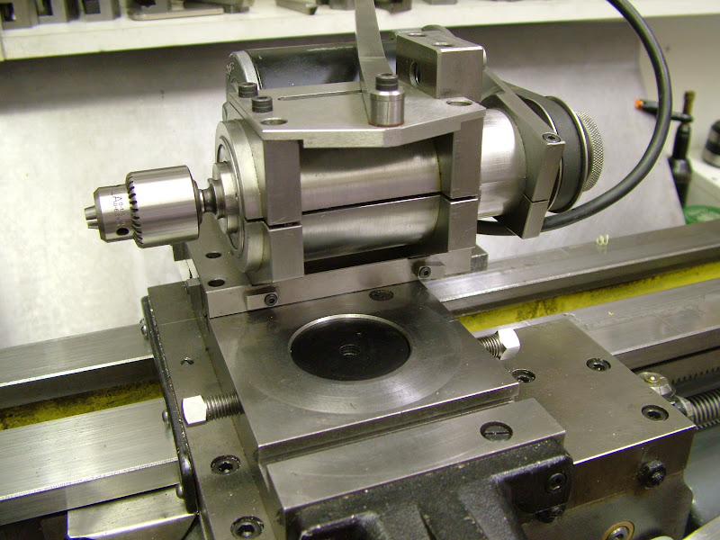
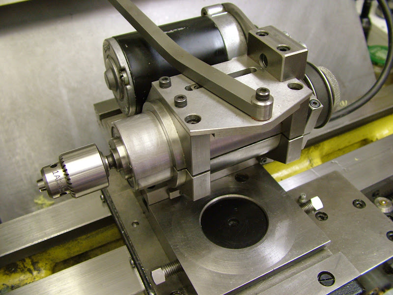
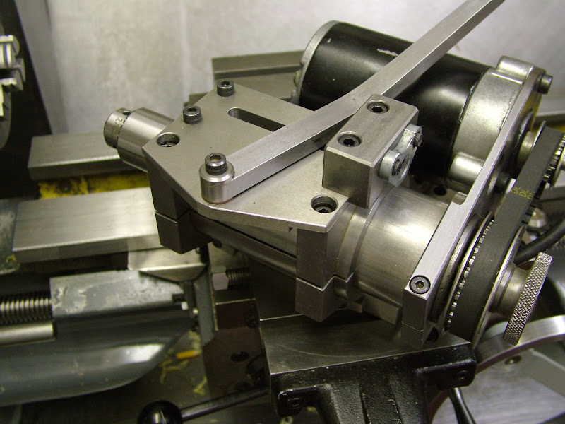
So far I have made three, the first rather light one was based on the spindle in the Sparey book - The Amateurs Lathe. The second, much heavier, infact too heavy for comfort with the cross slide wound out, was replaced by the last version made. It's my own design - no I'm afraid there are no drawings : - and has a much better spindle running in a quill to enable drilling at an angle. It's powered by a 24volt lorry fan heater motor running on a fixed voltage of about 18volts which is more than powerful for light milling with a 6mm cutter if a little fast. So far it has done all that's been asked of it and the other two have been passed on to friends.
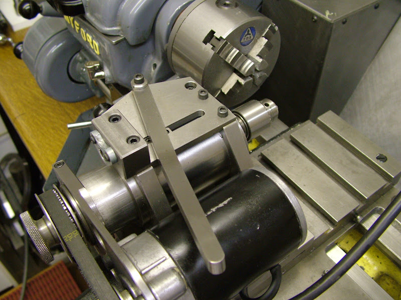
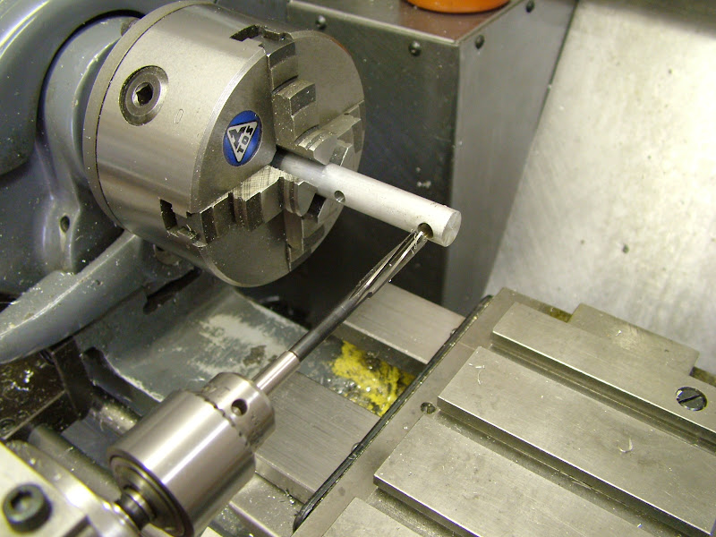
The spindle has back to back angular contact bearings at the front and a standard race at the back in which the shaft can float. The spindle taper is based on an R8 - straight shank with a simple taper and works very well. These first five pics show it in position for drilling toward the headstock - pic 5 has the spindle extended ........
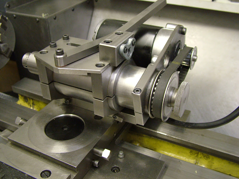
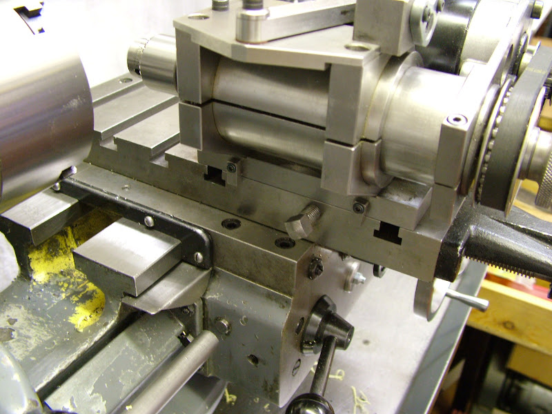
Moved through 90 degrees, set up is aided by two small dead stops that drop down depending which face is located toward the cross slide table
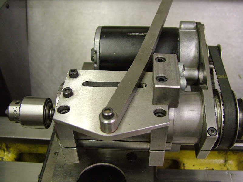
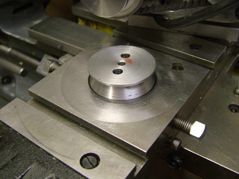
This boss can be bolted on to allow fitment to the topslide location to enable the attachment to be set at an angle
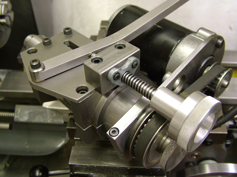
This leadscrew attachment for fine control when plunge milling was concieved in a hurry when milling the transfer ports in the ETA liners. It works well giving fine control. Return travel drive is by rubber band tension- really!
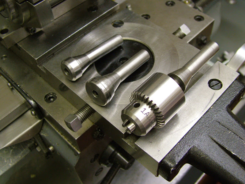
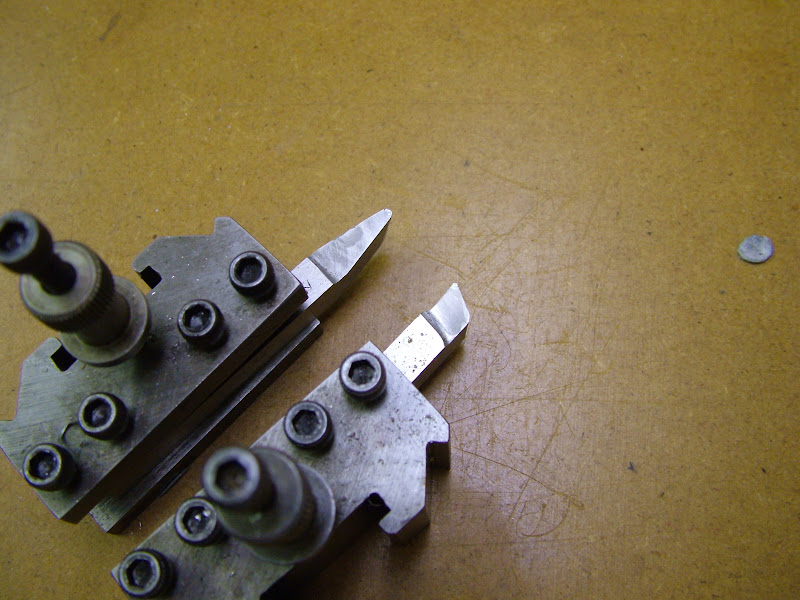
The three pieces of tooling, made from tool steel but unhardened. 6mm and 1/4" arbours and a 1/4" drill chuck
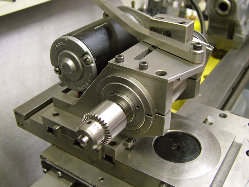
Details of the motor. Ideally this ought to be replaced with a small VFD set up but it's worked fine with this for this long - maybe when it burns out then ;D
https://lh4.googleusercontent.com/-ID2uaiRqol4/T-H9awD_l0I/AAAAAAAAGd4/kZOqpiFc_Zw
/s800/DSCF0575.JPG
There you are guys, hope thats what you wanted, nothing done today on the engine but tomorrow should see a start on the cylinder heads if I don't spend too long over at my friend Lee's (not difficult at all once we get together)
Regards for now - Ramon
It was from him I learnt the benefit of the cross slide drilling/milling attachment. "Make yourself one of these as soon as you can - you'll soon ask yourself just how you ever got on without one" going on to describe the ease of milling keyways dead on centre line, drilling holes around pitch circles etc etc. He even used his to cut keyways to quarter the wheels on the locos he built.
Well it took awhile before I did but he was right, you don't realise just how useful and versatile this is until you have one.
So far I have made three, the first rather light one was based on the spindle in the Sparey book - The Amateurs Lathe. The second, much heavier, infact too heavy for comfort with the cross slide wound out, was replaced by the last version made. It's my own design - no I'm afraid there are no drawings :
- and has a much better spindle running in a quill to enable drilling at an angle. It's powered by a 24volt lorry fan heater motor running on a fixed voltage of about 18volts which is more than powerful for light milling with a 6mm cutter if a little fast. So far it has done all that's been asked of it and the other two have been passed on to friends.The spindle has back to back angular contact bearings at the front and a standard race at the back in which the shaft can float. The spindle taper is based on an R8 - straight shank with a simple taper and works very well. These first five pics show it in position for drilling toward the headstock - pic 5 has the spindle extended ........
Moved through 90 degrees, set up is aided by two small dead stops that drop down depending which face is located toward the cross slide table
This boss can be bolted on to allow fitment to the topslide location to enable the attachment to be set at an angle
This leadscrew attachment for fine control when plunge milling was concieved in a hurry when milling the transfer ports in the ETA liners. It works well giving fine control. Return travel drive is by rubber band tension- really!
The three pieces of tooling, made from tool steel but unhardened. 6mm and 1/4" arbours and a 1/4" drill chuck
Details of the motor. Ideally this ought to be replaced with a small VFD set up but it's worked fine with this for this long - maybe when it burns out then ;D
https://lh4.googleusercontent.com/-ID2uaiRqol4/T-H9awD_l0I/AAAAAAAAGd4/kZOqpiFc_Zw
/s800/DSCF0575.JPG
There you are guys, hope thats what you wanted, nothing done today on the engine but tomorrow should see a start on the cylinder heads if I don't spend too long over at my friend Lee's (not difficult at all once we get together
)Regards for now - Ramon
arnoldb
Well-Known Member
- Joined
- Apr 8, 2009
- Messages
- 1,792
- Reaction score
- 12
:bow: My sentiments exactly !steamer said:Oh now that is SWEEEEET Ramon!
Kind regards, Arnold
- Joined
- Jan 30, 2011
- Messages
- 365
- Reaction score
- 72
Hi Guys, Hope those pics convey some of the versatility that that useful bit of kit has. Thoroughly recommended Thm: Thanks for the compliment too Jan but I lay no claim to being a 'Toolmaker'. Machinist? well maybe but 'toolmaker' most definitely not
Managed to get on with those cylinder heads - heres a few more pics of the machining - basic turning and milling but the sequence may be of use/interest to someone.........
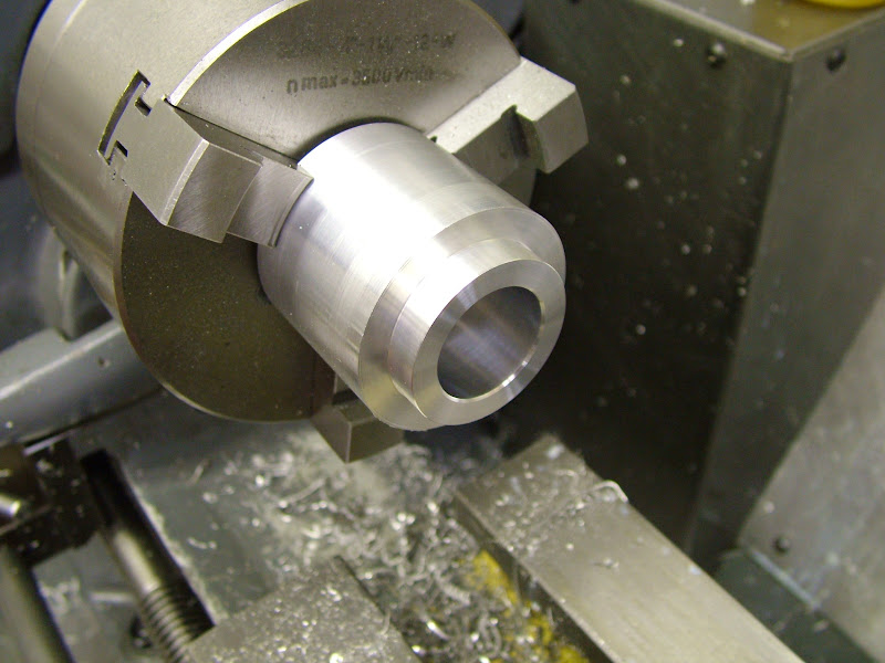
Began by roughing them out to plus 1mm all round, likewise the bores
Next op was to finish the bores - using a liner as a plug gauge - turning the rebate to finish size - and carefully centreing and drilling through 4.8 mm (large enough to get a 2BA allen key through required for the next op on yet another expanding mandrel))
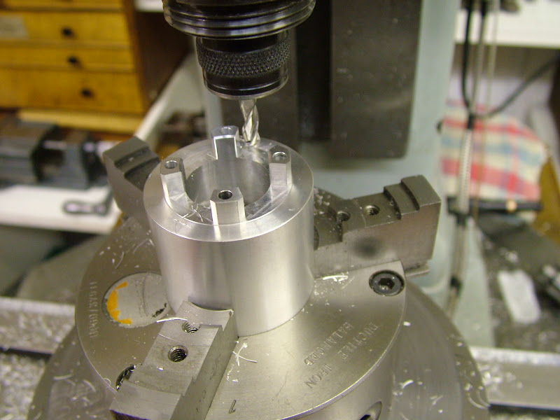
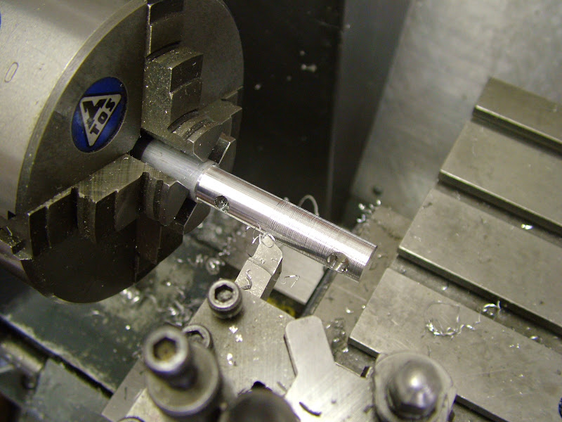
I went about drilling for the cylinder bolts differently to previous engines. On the Racers and Eta's the fins were cut first but on the Etas particularly the drill wandered very slightly. This was put down to the requirement of the drill to re-centre itself on each fin as it passed through even though the preceding fin was acting as a guide so this time the holes were put in first. Relatively speaking, these are 'deep holes' so they were drilled 3mm first with the drill pushed right back in the chuck to begin with to gain minimum deflection. The holes were drilled as deep as that would allow before extending the drill and drilling right through. They were then opened up with a 3.4 to give clearance on 5BA.
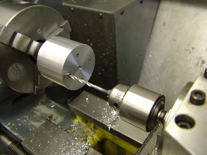
Despite the long hole to diameter ratio by not allowing the drill to crowd with swarf and keeping the pecks small no significant deflection occurred.
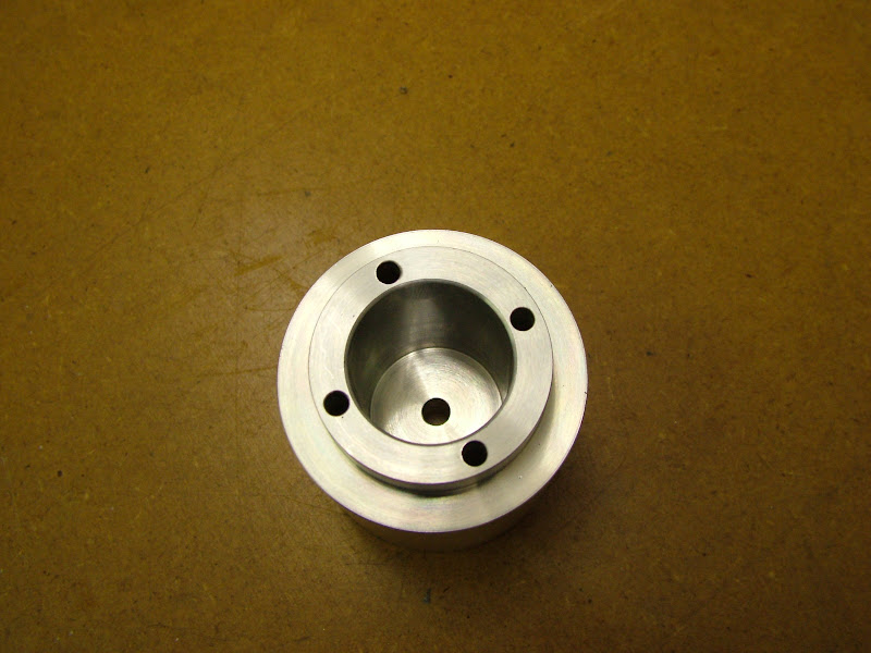
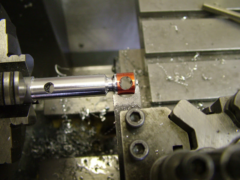
As the bolts are not yet made the head could not be tried on the case to check but by using the liner as a guide which had previously been checked on the case dropping four 5BA bolts in confirmed everything was fine
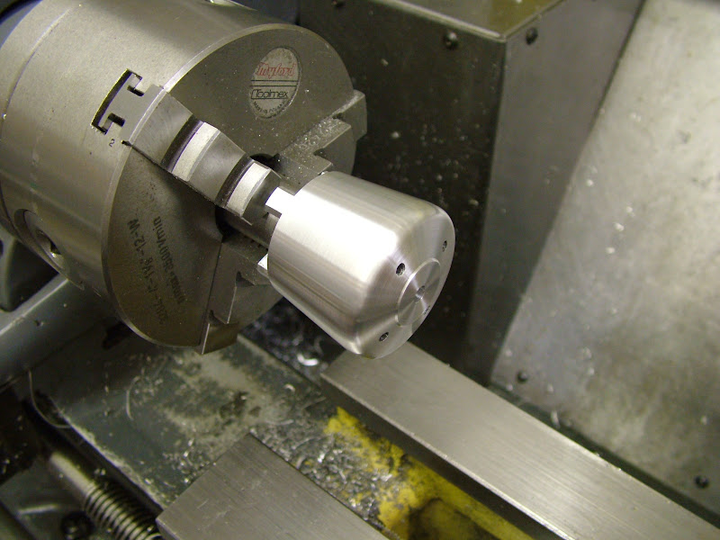
Next up was to mill around the base to leave the 'pedestals'......
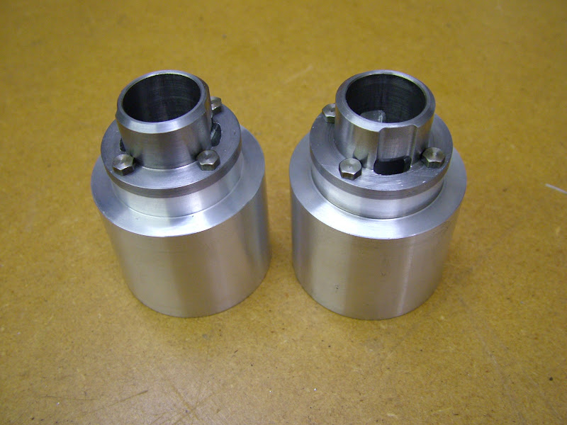
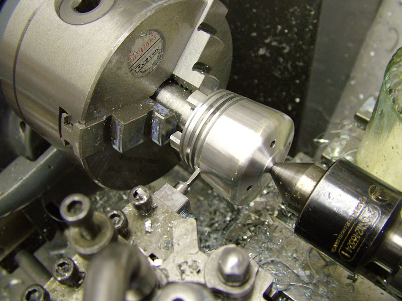
...before transfering back to the expanding mandrel for shaping the profile......
.... and cutting the fins. Once again the tool bit was ground up from a discarded FC3 6mm cutter shank to the width required (2.0mm) which performed admirably. The spacing was set by moving the dead stop each time then interspersing a 3.2 slip - 2mm gap, 1.2mm fin thickness. Depth of cut at the deepest was 8.3 mm
Finally the hole for the comp screw was trued using a 5mm FC3 cutter, drilled 5.3 and tapped 1/4 BSF then the bolt holes spot-faced to finish them off
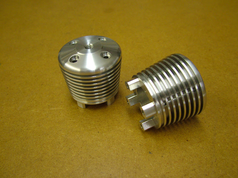
I must admit I had thought that the interupted cuts on cutting the fins caused by the bolt holes being there might create a problem but the cutter just sailed through. This way also had an unexpected bonus too in that there were no drill burrs on each fin to clean up as was the case previously, the burrs left on the sides of the bolt holes in the fin gaps literally flicked off with the end of a needle file. I will certainly use this sequence in the future.
Well there we go, a slightly new and beneficial process to me - hope thats of use to someone. The cases have been bead blasted and have come up really well but you'll have to wait for final assembly for seeing them - minimal handling until assembly from now on. Next up I think, will be the con-rods
Regards for now - Ramon
Managed to get on with those cylinder heads - heres a few more pics of the machining - basic turning and milling but the sequence may be of use/interest to someone.........
Began by roughing them out to plus 1mm all round, likewise the bores
Next op was to finish the bores - using a liner as a plug gauge - turning the rebate to finish size - and carefully centreing and drilling through 4.8 mm (large enough to get a 2BA allen key through required for the next op on yet another expanding mandrel))
I went about drilling for the cylinder bolts differently to previous engines. On the Racers and Eta's the fins were cut first but on the Etas particularly the drill wandered very slightly. This was put down to the requirement of the drill to re-centre itself on each fin as it passed through even though the preceding fin was acting as a guide so this time the holes were put in first. Relatively speaking, these are 'deep holes' so they were drilled 3mm first with the drill pushed right back in the chuck to begin with to gain minimum deflection. The holes were drilled as deep as that would allow before extending the drill and drilling right through. They were then opened up with a 3.4 to give clearance on 5BA.
Despite the long hole to diameter ratio by not allowing the drill to crowd with swarf and keeping the pecks small no significant deflection occurred.
As the bolts are not yet made the head could not be tried on the case to check but by using the liner as a guide which had previously been checked on the case dropping four 5BA bolts in confirmed everything was fine
Next up was to mill around the base to leave the 'pedestals'......
...before transfering back to the expanding mandrel for shaping the profile......
.... and cutting the fins. Once again the tool bit was ground up from a discarded FC3 6mm cutter shank to the width required (2.0mm) which performed admirably. The spacing was set by moving the dead stop each time then interspersing a 3.2 slip - 2mm gap, 1.2mm fin thickness. Depth of cut at the deepest was 8.3 mm
Finally the hole for the comp screw was trued using a 5mm FC3 cutter, drilled 5.3 and tapped 1/4 BSF then the bolt holes spot-faced to finish them off
I must admit I had thought that the interupted cuts on cutting the fins caused by the bolt holes being there might create a problem but the cutter just sailed through. This way also had an unexpected bonus too in that there were no drill burrs on each fin to clean up as was the case previously, the burrs left on the sides of the bolt holes in the fin gaps literally flicked off with the end of a needle file. I will certainly use this sequence in the future.
Well there we go, a slightly new and beneficial process to me - hope thats of use to someone. The cases have been bead blasted and have come up really well but you'll have to wait for final assembly for seeing them - minimal handling until assembly from now on. Next up I think, will be the con-rods
Regards for now - Ramon
- Joined
- Jan 30, 2011
- Messages
- 365
- Reaction score
- 72
Despite what it may look like Dave - other than looking for a reasonable finish from the tool as it's cutting it's not particularly strived for and certainly not 'worked at' to achieve.
I have no means to grind tools other than an off-hand grinder so that's how they are formed. Usually it's with a reluctance to stop and create a decent tool that whatever's there gets pressed into service. I confess that I'm quite lazy when it comes to grinding new tools, on some shots I'm quite surprised that no one picks up on the apparent poor quality of the tool bit in use That said it is only the very tip that does the work and for most of the time, and certainly on these engine parts - steel as well as ali - these two tools got quite a bit of time in. Despite exhibiting all the wrong rake angles for these differing materials they do work rather well.
Although there are many other bits of hacked about HSS lying around these two seem to have acquired a 'favourite' status. (Ignore the 'wart', it was still there from stopping the cylinders rolling about)
The tapers on these cylinders were cut using the round nosed tapered tool, the last, very fine, cut carried out on the 'back stroke'. The radius was applied by three chamfered faces and faired using the same tool as on the spinners then a very light application of 400 grit wet and dry using paraffin as a lube to finish them off - that's all, nothing else - then, after the fins were cut and very lightly chamfered, a piece of Garryflex block was held lightly on each fin.
Brock, I don't know if I can match the original colour as per the images I have but it will certainly be red - as things are going I guess that will be in about a fortnight.
Regards for now - Ramon
I have no means to grind tools other than an off-hand grinder so that's how they are formed. Usually it's with a reluctance to stop and create a decent tool that whatever's there gets pressed into service. I confess that I'm quite lazy when it comes to grinding new tools, on some shots I'm quite surprised that no one picks up on the apparent poor quality of the tool bit in use
That said it is only the very tip that does the work and for most of the time, and certainly on these engine parts - steel as well as ali - these two tools got quite a bit of time in. Despite exhibiting all the wrong rake angles for these differing materials they do work rather well.
Although there are many other bits of hacked about HSS lying around these two seem to have acquired a 'favourite' status. (Ignore the 'wart', it was still there from stopping the cylinders rolling about)
The tapers on these cylinders were cut using the round nosed tapered tool, the last, very fine, cut carried out on the 'back stroke'. The radius was applied by three chamfered faces and faired using the same tool as on the spinners then a very light application of 400 grit wet and dry using paraffin as a lube to finish them off - that's all, nothing else - then, after the fins were cut and very lightly chamfered, a piece of Garryflex block was held lightly on each fin.
Brock, I don't know if I can match the original colour as per the images I have but it will certainly be red - as things are going I guess that will be in about a fortnight.
Regards for now - Ramon
- Joined
- Jan 30, 2011
- Messages
- 365
- Reaction score
- 72
Hi there guy's - had a real good day in the shop today- two con-rods, two comp screws and a start on the cylinder head bolts - not much left to do now ;D
Prior to doing the Eta engines I had always fought shy of turned con -rods because of the perceived difficulty of dealing with the 'second' ball end. In fact when drawing the Etas the rods were done as rectangular section. However the S&J version had to have a turned one and the following method evolved :idea: It proved so successful the two blanks for the other two Etas were discarded and they then had the 'correct' turned rods too.
A few more pics then......
The material used for the rods is HE15 aluminium. This is the first time I have used this and found it easy to machine producing a good finish. Going by the 'feel of things' it's not as tough as the Alumec 89 used previously for these parts but it's a recommended grade for con rods so I'm fairly certain it will handle the task.
Apart from drilling the oil hole the rods were made entirely on the lathe, the holes for the big and small ends drilled and reamed using the milling attachment, the big end toward the tailstock. I have convinced myself today that a VFD motor would definitely be an improvement - the unit is too fast for reaming so that has to be done by turning the spindle by the draw bar knurled wheel with one hand and turning the cross slide at the same time with the other. Bit like patting your head and rubbing your tum but it works.
The bar was then reduced - that tool again, cutting on the 'back stroke'
A couple of radius tools were milled from gauge plate (GFS) and hardened but not tempered. I find setting this equal about the hole is easily done by marking up and getting the land each side equal before plunging the tool in.
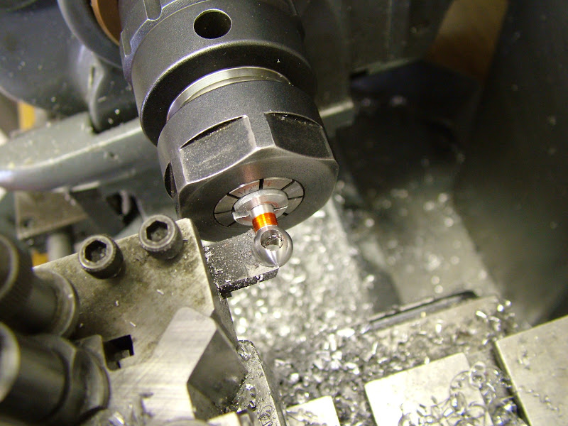
The OD of the rod was turned .2mm up so as that ink fades in the centre of the radius there's just .1mm left. Once it fades the inward movement stops leaving the tool to take the spring out of the cut which just about takes care of that .1mm
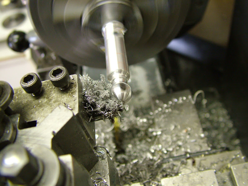
Next is to turn the shaft taper and flare in to the big end leaving sufficient for shaping the little end on the next op. If doing more than one it pays to make a note of the settings.
A quick whizz with some 400 grit wet and dry, paraffin and oil and a piece of Garryflex and its ready to part off.
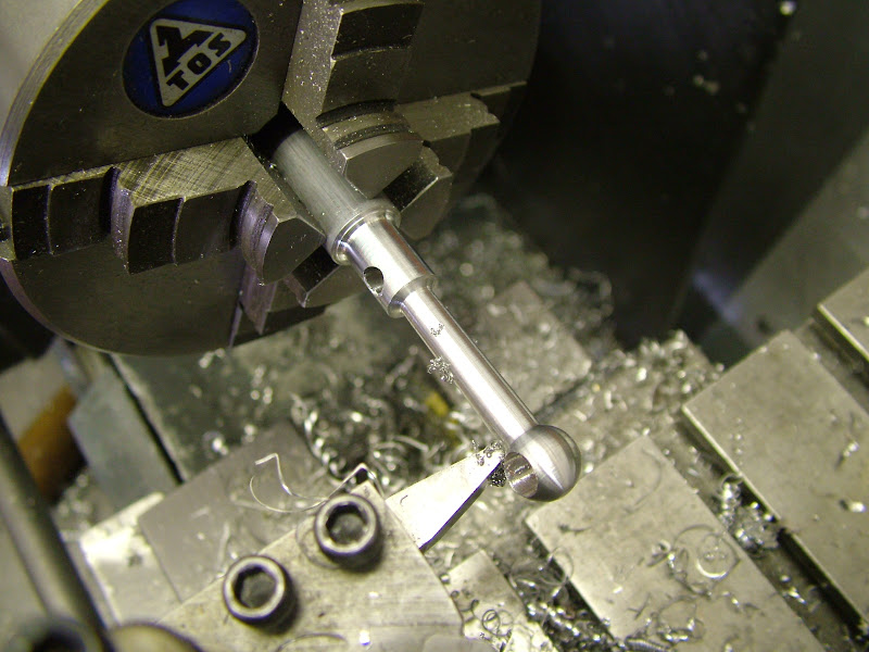
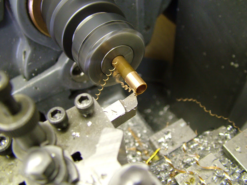
Next up was to take a short (about 18mm) length of 1/2" ali and face each end. The con rod was measured across the shank about 18mm up from the big end and a drill of this size was run through. It was then bored at the same taper as the rods so that the taper ran out as it reached the far end. Quickly smoothed with some 400 on a stick it was then cut in half and deburred.
The rod can now be held in the collet chuck with sufficient grip to radius the small end
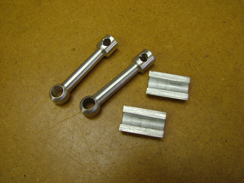
A couple of drawn Phosphor Bronze bushes were turned for the big ends. Reamed 6mm, the OD's are .02mm up such that once pressed home the bore requires slight lapping to achieve a precise fit on the crank pin
Finished save one small op and two more radius tools. Despite all those made for the Waller and Etas engine not one of the radii required :
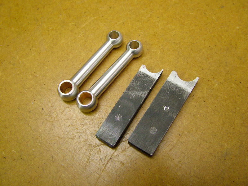
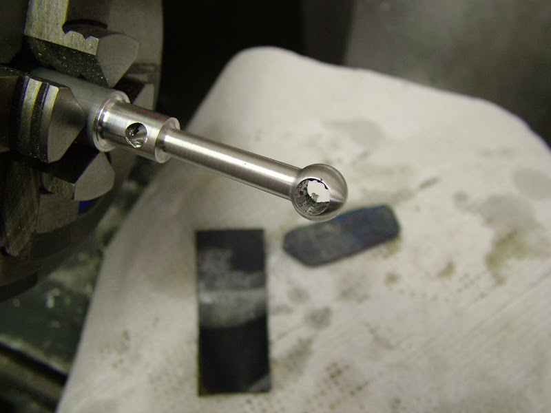
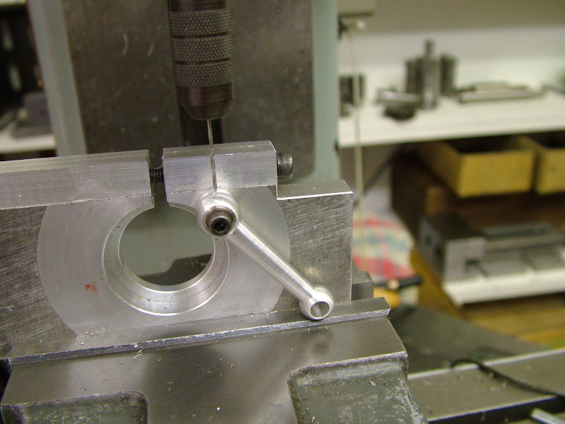
That last op then was to drill the oil hole in the big end. Held in place on a small bush by hand, the angle determined by resting on the vise jaw.
Well that's another couple of parts finished. Once the head bolts are done the spray bars and needle valves will get tackled next to get the brass out of the way before finally lapping the liner and making the pistons. Not long to go now at all
Regards for now - Ramon
Prior to doing the Eta engines I had always fought shy of turned con -rods because of the perceived difficulty of dealing with the 'second' ball end. In fact when drawing the Etas the rods were done as rectangular section. However the S&J version had to have a turned one and the following method evolved :idea: It proved so successful the two blanks for the other two Etas were discarded and they then had the 'correct' turned rods too.
A few more pics then
......The material used for the rods is HE15 aluminium. This is the first time I have used this and found it easy to machine producing a good finish. Going by the 'feel of things' it's not as tough as the Alumec 89 used previously for these parts but it's a recommended grade for con rods so I'm fairly certain it will handle the task.
Apart from drilling the oil hole the rods were made entirely on the lathe, the holes for the big and small ends drilled and reamed using the milling attachment, the big end toward the tailstock. I have convinced myself today that a VFD motor would definitely be an improvement - the unit is too fast for reaming so that has to be done by turning the spindle by the draw bar knurled wheel with one hand and turning the cross slide at the same time with the other. Bit like patting your head and rubbing your tum but it works.
The bar was then reduced - that tool again, cutting on the 'back stroke'
A couple of radius tools were milled from gauge plate (GFS) and hardened but not tempered. I find setting this equal about the hole is easily done by marking up and getting the land each side equal before plunging the tool in.
The OD of the rod was turned .2mm up so as that ink fades in the centre of the radius there's just .1mm left. Once it fades the inward movement stops leaving the tool to take the spring out of the cut which just about takes care of that .1mm
Next is to turn the shaft taper and flare in to the big end leaving sufficient for shaping the little end on the next op. If doing more than one it pays to make a note of the settings.
A quick whizz with some 400 grit wet and dry, paraffin and oil and a piece of Garryflex and its ready to part off.
Next up was to take a short (about 18mm) length of 1/2" ali and face each end. The con rod was measured across the shank about 18mm up from the big end and a drill of this size was run through. It was then bored at the same taper as the rods so that the taper ran out as it reached the far end. Quickly smoothed with some 400 on a stick it was then cut in half and deburred.
The rod can now be held in the collet chuck with sufficient grip to radius the small end
A couple of drawn Phosphor Bronze bushes were turned for the big ends. Reamed 6mm, the OD's are .02mm up such that once pressed home the bore requires slight lapping to achieve a precise fit on the crank pin
Finished save one small op and two more radius tools. Despite all those made for the Waller and Etas engine not one of the radii required :
That last op then was to drill the oil hole in the big end. Held in place on a small bush by hand, the angle determined by resting on the vise jaw.
Well that's another couple of parts finished. Once the head bolts are done the spray bars and needle valves will get tackled next to get the brass out of the way before finally lapping the liner and making the pistons. Not long to go now at all
Regards for now - Ramon
- Joined
- Jan 30, 2011
- Messages
- 365
- Reaction score
- 72
Hi Guys thanks for your kind comments - it's very pleasing to hear that what's posted is of use to someone. It certainly makes the time posting takes up all the more worthwhile.
Not much to report, progress today was a bit like being back at work - sixteen 5BA bolts/screws for the heads and front plates turned from 6mm En1a. Not exactly scintillating and nothing grand on the scale of such things but it's been quite while since anything remotely repetitive was done.
I did however get a slight distraction from that
Some pics of an Eta running are required 'for something else' so it didn't take much persuasion to get the test stand out.......
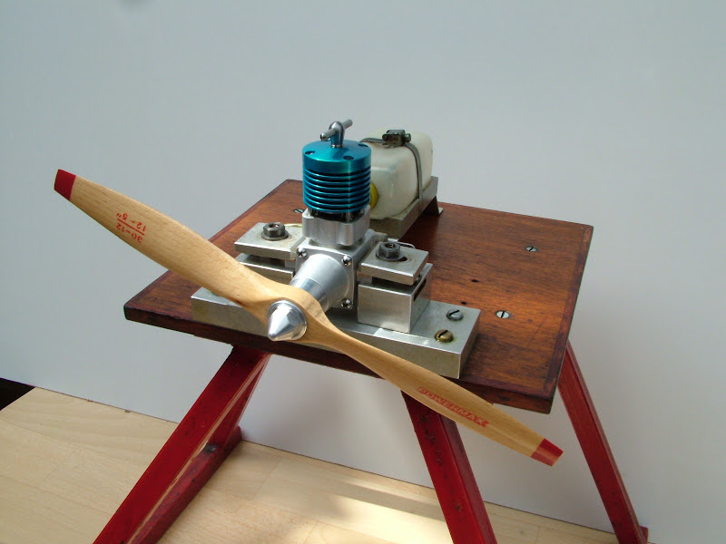
.......and fire it up woohoo1
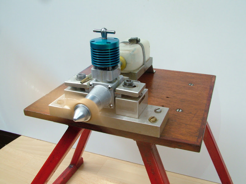
With a good exhaust prime and one choke turn it fired on the third flick and was away;D ;D ;D ;D ;D ;D
Oh' "Don't ya just love the smell of fresh diesel fuel in the morning"
Needle valve assemblies next - back soon
Regards - Ramon
Not much to report, progress today was a bit like being back at work - sixteen 5BA bolts/screws for the heads and front plates turned from 6mm En1a. Not exactly scintillating and nothing grand on the scale of such things but it's been quite while since anything remotely repetitive was done.
I did however get a slight distraction from that
Some pics of an Eta running are required 'for something else' so it didn't take much persuasion to get the test stand out.......
.......and fire it up woohoo1
With a good exhaust prime and one choke turn it fired on the third flick and was away;D ;D ;D ;D ;D ;D
Oh' "Don't ya just love the smell of fresh diesel fuel in the morning"
Needle valve assemblies next - back soon
Regards - Ramon
seagar
Well-Known Member
- Joined
- Apr 3, 2008
- Messages
- 291
- Reaction score
- 5
Oh yes,I know and remember that smell as a pit man in my racing days.W0W that ETA is beautifull.
Iam enjoying this build more than any other I have followed.Most of my team racing was done with ETA & Super Tigre,so this adds to my interest. Thanks for sharing your skills with us . :bow: :bow: :bow:
Regards ,Ian (seagar).
Iam enjoying this build more than any other I have followed.Most of my team racing was done with ETA & Super Tigre,so this adds to my interest. Thanks for sharing your skills with us . :bow: :bow: :bow:
Regards ,Ian (seagar).
Beautiful, simply a work of metal art. I am always amazed at how much I learn from these post and perfect pictures. You are truly in a class with very few Ramon. I check a couple times a day just to see if you have any updates. Please continue thanks, Brian
Similar threads
- Replies
- 18
- Views
- 8K
- Replies
- 3
- Views
- 3K
- Replies
- 172
- Views
- 80K