- Joined
- Jan 30, 2011
- Messages
- 365
- Reaction score
- 72
After finishing the Eta engines it was intended to follow those with this project but somehow that intention got waylaid by the Waller engine and other extraneous factors that occurred late last year and into this one :") At last though, after what seems like an eternity due to one distraction or another, it looks like I'm finally in a position to begin working on another 5cc version of a 'diesel' model aircraft engine ;D
At last though, after what seems like an eternity due to one distraction or another, it looks like I'm finally in a position to begin working on another 5cc version of a 'diesel' model aircraft engine ;D
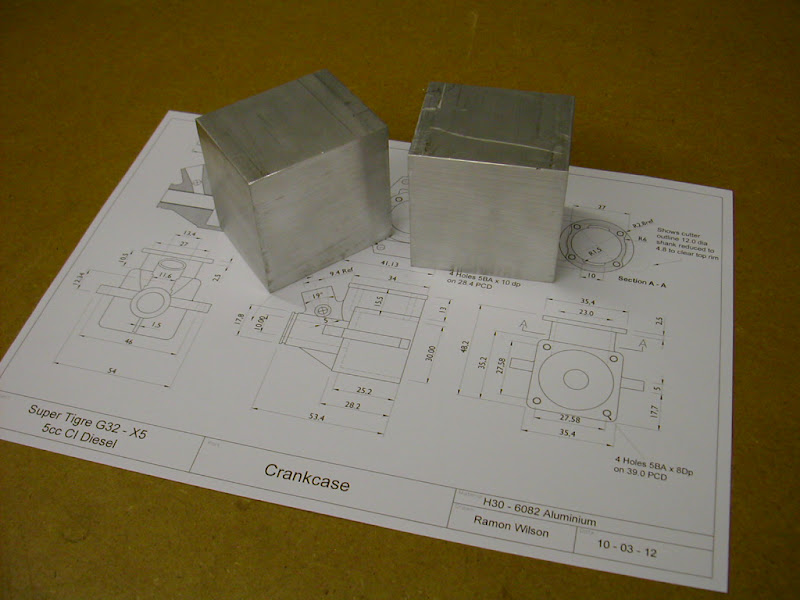
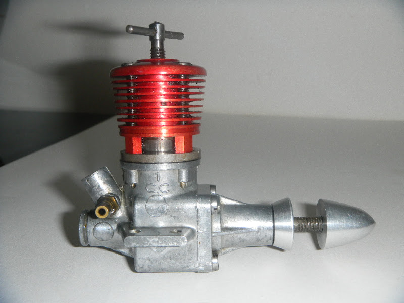
The one chosen for scaling up this time is a small 1cc engine produced by Super Tigre in the fifties. ST also produced 1.5 and 2.5 cc versions on similar lines - ie rear intake drum valve induction with bolt on ball raced front housings - single for the 1 and 1.5cc and, I believe, twin for the 2.5cc. Here are a couple of images of the original. These were supplied by Ernesto Pizzi of Messina in Italy who kindly agreed to take several views of his engine for me. Ernesto also assisted with measuring and providing dimensions of his original as well as comparing the new drawings to the original dimensions
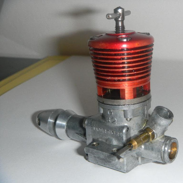
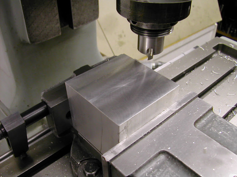
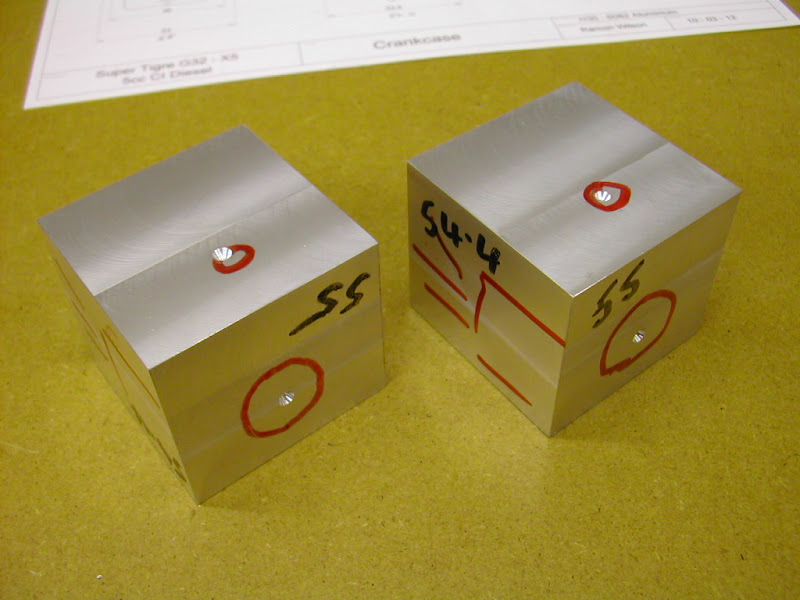
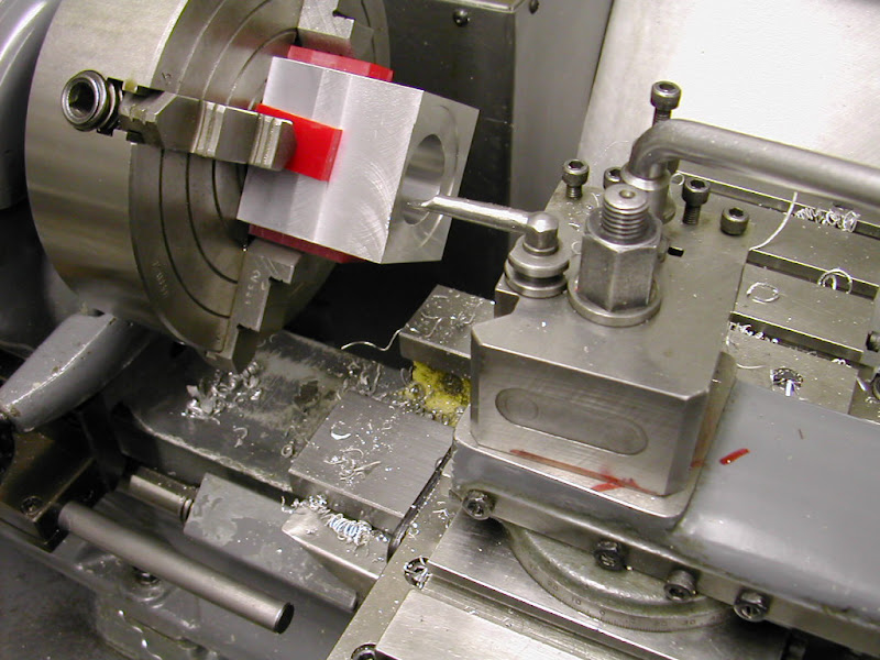
As can be seen the original crankcase is a die casting and is going to present some challenges to machine it from solid particularly around the intake area ( No CNC I'm afraid, just basic kit available). However with carefull set ups and a bit of fettling with a rotary burr in strategic places I feel a reasonable representation can be achieved without too many compromises which will, hopefully, convey the lines of this very characterful little engine.
Why 5cc? well for me it's a good size to handle, not too small to be fiddly especially on the smaller parts and not so big as to require sourcing larger lumps of material. They swing a decent sized prop and make a lovely sound too. I know there can be some problems with sourcing fuel for some but for me no glo motor gives off an aroma like a diesel does ;D
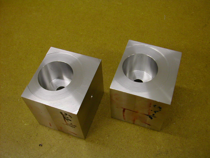
Materials are reasonably basic - He 30 ali for the case, front housing and head and, as with previous engines, En1a leaded steel will be used for the liner with a cast iron piston and the crankshaft made from En24T.
Making these engines is not a long term commitment. They have a low part count but the machining does have to be accurate with good - and in the case of the piston liner fit, exceptional tolerances but it is all achievable with easilly made kit and when it bursts into life at the end, well ;D ;D ;D ;D
There doesn't appear to be too many threads on here for such a project so I don't know if this will appeal to members but if there are any interested in making such engines as before I'm quite happy to share this build on here with you.
On that note then I have done a set of drawings for all parts but have just realised I do not know how to get them on here as PDF attachments. I have them converted to PDF so if someone could point me in the right direction (please keep it as simple and straightforward as possible) it would be appreciated and I'll get them posted so you can see what's what.
Regards for now - Ramon
At last though, after what seems like an eternity due to one distraction or another, it looks like I'm finally in a position to begin working on another 5cc version of a 'diesel' model aircraft engine ;D The one chosen for scaling up this time is a small 1cc engine produced by Super Tigre in the fifties. ST also produced 1.5 and 2.5 cc versions on similar lines - ie rear intake drum valve induction with bolt on ball raced front housings - single for the 1 and 1.5cc and, I believe, twin for the 2.5cc. Here are a couple of images of the original. These were supplied by Ernesto Pizzi of Messina in Italy who kindly agreed to take several views of his engine for me. Ernesto also assisted with measuring and providing dimensions of his original as well as comparing the new drawings to the original dimensions
As can be seen the original crankcase is a die casting and is going to present some challenges to machine it from solid particularly around the intake area ( No CNC I'm afraid, just basic kit available). However with carefull set ups and a bit of fettling with a rotary burr in strategic places I feel a reasonable representation can be achieved without too many compromises which will, hopefully, convey the lines of this very characterful little engine.
Why 5cc? well for me it's a good size to handle, not too small to be fiddly especially on the smaller parts and not so big as to require sourcing larger lumps of material. They swing a decent sized prop and make a lovely sound too. I know there can be some problems with sourcing fuel for some but for me no glo motor gives off an aroma like a diesel does ;D
Materials are reasonably basic - He 30 ali for the case, front housing and head and, as with previous engines, En1a leaded steel will be used for the liner with a cast iron piston and the crankshaft made from En24T.
Making these engines is not a long term commitment. They have a low part count but the machining does have to be accurate with good - and in the case of the piston liner fit, exceptional tolerances but it is all achievable with easilly made kit and when it bursts into life at the end, well ;D ;D ;D ;D
There doesn't appear to be too many threads on here for such a project so I don't know if this will appeal to members but if there are any interested in making such engines as before I'm quite happy to share this build on here with you.
On that note then I have done a set of drawings for all parts but have just realised I do not know how to get them on here as PDF attachments. I have them converted to PDF so if someone could point me in the right direction (please keep it as simple and straightforward as possible) it would be appreciated and I'll get them posted so you can see what's what.
Regards for now - Ramon