Stuart Turner boiler feed pump

Home Model Engine Machinist Forum

Help Support Home Model Engine Machinist Forum:

This site may earn a commission from merchant affiliate links, including eBay, Amazon, and others.

Marty Feldman

Well-Known Member
Joined
Nov 24, 2009
Messages
59
Reaction score
5
Has anyone here done the little S-T pump? I have a question about the function of a steam passage shown on the print.
-Marty, in Owl's Head, Maine-
 
Hello Marty

I've recently acquired some castings for the Stuart Pump and am also puzzling out how it works and how to machine the parts.

The drawing I have is #90085 and is dated 26 November 1976. There are however differences in dimensions and methods between the casting set I have and this drawing.

If you can identify the passages I'll try and help with the explanation.

Regards
John ???
 
Hi Marty

If you can add an image of the section on the print showing the part with the mystery passage, it will help others to help you.

Kind regards, Arnold
 
Do post a section of the drawing and circle the passage way you are unsure of. If it is the manual feed pump to which you refer, it can't be too difficult for us to figure out. I might also be able to figure it out based on the plans for the Stuart triple that I'm building which includes two pumps (water and air). The pumps on the triple look a little different than the manula feed pump, but I suspect they function pretty much the same internally. Other than being unsure how much clearances to allow for the pistons, I have had no trouble decoding the drawings and the vrious passage ways.

Robin
 
If you mean the single cylinder steam driven pump, I built one years ago. I have the plans stashed someplace, so fire away with questions.
 
The pump is a single cylinder steam pump. The 2 pictures below are from the print that came with the Stuart turner castings. It does not have a number or a date, but it is an original ST print.

STPump-ValveChest.jpg


STPump-Cyl.jpg


The upper picture shows the valve chamber. A mystery to me has to do with the 'T' shaped passage I have hand-colored in red, somewhat faintly, on the left side of the drawing. The short vertical stem of the 'T' is the steam-in to the pump. The longer horizontal part of the 'T' shows two very small holes, one on the left and one on the right, drilled at right angles to the longer horizontal part of the 'T'. They look like little black dots on the print. What are those 2 holes for?

The second of the two pictures shows the cylinder to which the valve chest mates.

Sorry about the miserable resolution of the photographs. I can no longer get Photobucket to behave as it used to. Doing a digitized scan of the print might be the right avenue for conveying a clear image.
 
MF,

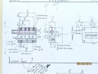
Having blown them up a little and sharpened as well, it is still rather difficult to read.

The conclusion that I came to is that it is the steam inlet (the small piece of the 'T') and a spool (piston) valve goes into the long part of the 'T'.

As the piston valve is moved in and out by the piston rod of the main cylinder (going to the pump itself) it will feed steam to either end of the cylinder, making the piston go in and out. Basically, a piston valve engine.

So turn on steam, and the unit will just go backwards and forwards, driving the pump on the other end of the main piston rod, whilst at the same time, moving the spool valve so that feeds steam to the top and bottom of the piston and so on and so on and so on......................... continuous motion, and water pumped, until steam is cut off.

John
 
The valve worked from this piston rod controls a loose shuttle valve which in turn controls the steam distribution to the
cylinder. I have not made one of these (though I have often thought of doing so - some time) so I cannot be of more help without
a better look at the drawings, including the valves.

This may help a bit:

http://www.modelboatmayhem.co.uk/forum/index.php?topic=29412.0
 

Hi Marty,

In answer to your question ( WHAT ARE THE 2- HOLES FOR ) the 2- holes that you wish to know about are exhaust ports, they link up to the 2- holes on the face of the cylinder and connect to the exhaust outlet via the 'T' shaped dotted drilled holes going to the 3/16 x 40 tapped outlet.
If you look on the cross sectional plan of the steam chest the 2- 20deg holes coming in from each end of the 1/4" dia shuttle valve hole this carries the exhaust from the piston up thro" the shuttle valve and then transfers to the cylinder exhaust holes.

When you make the 5/32" dia auxiliary valve keep the edges a sharp as possible with dimensions strickland to the drawing, like wise on the shuttle valve.
Hope this answers your question.

Geo.
 

Latest posts

Back
Top