Stuart No. 4 build

Home Model Engine Machinist Forum

Help Support Home Model Engine Machinist Forum:

This site may earn a commission from merchant affiliate links, including eBay, Amazon, and others.

smfr

Project of the Month Winner!!!
Project of the Month Winner
Joined
Oct 29, 2011
Messages
287
Reaction score
2
I've started work on a set of Stuart No. 4 castings that I was lucky to pick up on eBay:


It has the crank as a casting, which I guess means that it's an older set? As far as I know, all the parts are present. I also have a casting kit for the reverse gear.

 
Step 1! The boxbed:


This is just basic squaring up on the milling machine, though space on my milling table is limited so clamping gets slightly interesting:


There's a shim under the lowest corner to stop it rocking. Once the underside is done, we flip it over and mill the top side flat:


Here I have to move clamps around, because I don't have enough travel. Note the 'L' on the lowest corner (found on the surface plate with a height gauge), so I know what height to start the cutter at.

I was hoping one of the "No. 4" imprints on the castings remains on the final model, but I suspect they all get cut off.


Next up, the soleplate. Again I had to get creative with clamping due to limited table space:


Note the stacked clamps! It's suboptimal because the whole thing could swivel around the one bolt, but the rotational forces are minimal when just trimming the bottom.

Once the bottom was flat, I flipped it over and went over the top surface, then cut the bearing slots. Here I messed up slightly: rather than center the slots on the entire casting, I started by centering them on the bearing bosses, but then found that those bosses are not centered, so I had to correct slightly. The slots are a bit oversize, but it's not an issue as I just cut the bearings to fit.


While it was clamped down, I also drilled and spotfaced the holes for the corner bolts. The plan doesn't show the spotfacing, but it's certainly required for the nuts to sit flat.

In the photo above I've completed one bottom bearing, making it a snug fit to the slot. Here's the other bearing being squared up:


I swear this gunmetal squirms under the cutter. I was pretty sure I'd cut the slots on these bearings within a thou or so, but the slot ended up about 2.5 thou too narrow. I took these to final size by filing, since I wanted them to be a snug fit to the soleplate.
 
I have been eyeballing the Stuart engines and I will follow along on your build. Are the casting all metal on frame, flywheel and cylinder.

Regards Don
 
The top bearings are a little more tricky. First I cleaned up the lower surface in the 4-jaw:


I then glued the two together, planning to turn the bosses. However, I realized that I had no true surface I could use to ensure that the join was aligned the turning axis, and in the center. So after some application of heat to undo the Superglue, I used a chuck spider in the 4-jaw to put a small flat on top of each bearing, with the bearings having the same thickness:


and then I could glue them together again:


The boss is then a simple turning job:


I also drilled a small hold down the center to I had a reference to re-center when I flipped it around. However, even with the best of plans...

At some point in the hole drilling, the Superglue gave way and the two sides separated. :mad:

Also, look at that hole! It's all over the place, and (I think) not just after separation:


After some futzing around trying to get the halves aligned properly, I attached them together with solder this time, and was able to complete the other side, and open up the hole to 1/4":


I'm wondering how to ensure that things are lined up when I drill and ream the hole to size. My plan is something like this:

1. Sweat the two lower bearings together and drill to 1/4", so that both upper and lower bearings have 1/4" holes in roughly the right spot. Separate the halves.
2. Sweat the tops and bottoms together in pairs, aligning the holes
3. Drill to 27/64"
4. Drill and tap the soleplate for the hold-down bolts, and bolt the bearings down
5. Ream in place with a spiral 7/16" reamer

Does that sound reasonable?
 
Don1966 said:
I have been eyeballing the Stuart engines and I will follow along on your build. Are the casting all metal on frame, flywheel and cylinder.

Hi Don

Frame (boxbed, soleplate, standard), flywheel and cylinder are all cast iron castings, yes.
 
I also love stuart engines and will follow with great interest. Really liked your beam engine repair thread. Great start on the number 4.

Bronson
 
This brings back memories. I built a Stuart No. 4 when I was in the 8th grade. It took a long time, as it was my first model and I had no milling machine (or milling attachment at first). I built it using a South Bend 9" Model A and a drill press. That was nearly 40 years ago. It had a forged crank. The model still lives on a shelf in my office. I look at some of the alignments and fits and cringe, but that's what experience does to you.
 
Please get some good photo shots of how you bore the shaft bearings. I would try to line them up on the mill after bolting them to the base plate and drill and ream them through if height is not a problem. I have not done this before so I am curious. I like your lathe spider I need to make my own. Good progress so far thanks for pointing out the mistakes.

Don
 
Hi SM', First of all let me begin by saying I really enjoyed watching your re-work of that Stuart beam engine, that was some very good work. An I have to agree with Don about drilling/reaming that C.S. hole on the mill. If you have an angle plate, bolt the base casting, with the bearings attached to it, and proceed that way. Both holes will then be in exact alignment and at the correct center height. I'm watching with interest and look forward to your progress.

BC1
Jim
 
Not too much progress over the past week. I think I've got as far as I can with the bearings until I receive the 7/16" spiral reamer I got on Ebay. Here's where I'm at:


The upper bearings were separated, then spot-faced with a 7/16" end mill and drilled. I have yet to tidy up the ends, but know that I'll use the rounding table, and pivot around the opposite bolt hole.

I still need to sweat the two lower bearings together to start the hole. Then I think I'll sweat uppers and lowers together and clean up the hole, then put them in the sole plate to see if things line up. I have a feeling that if I drill and ream them in place in the sole plate, the lower bearing is going to be oversize or misaligned. Maybe I'll do a dry-run or two at a smaller diameter to see how things work out.
 
".....Maybe I'll do a dry-run or two at a smaller diameter to see how things work out..."


A very wise course of action. :bow:

Dave
 
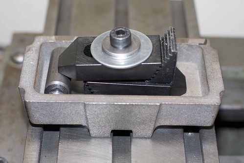
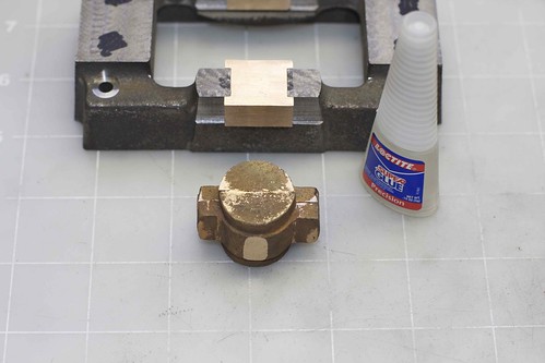
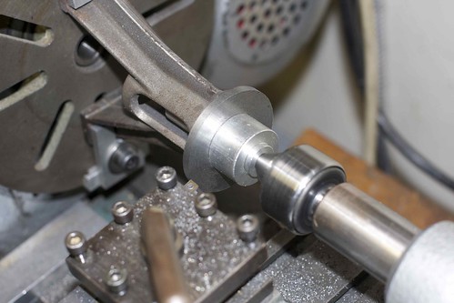
I thought I'd take a break from the bearings, and made some progress on the standard over the weekend. After some cleanup with a file, I wrung it onto lap that I had lying around:


which allowed me to do some initial cleanup on the feet. This setup isn't rigid enough to do a good job, but I just wanted to get the feed good enough for the next step. I'll finish them off later.

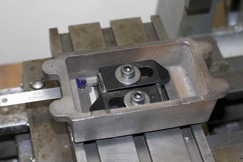
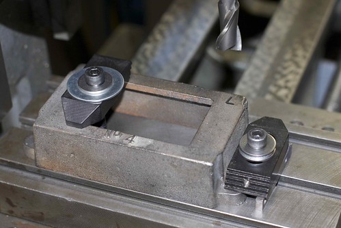
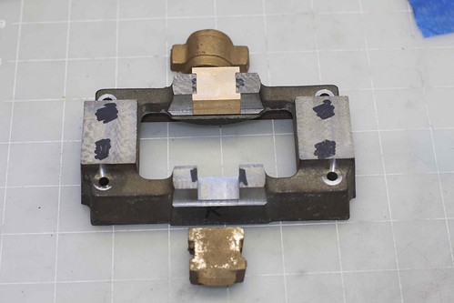
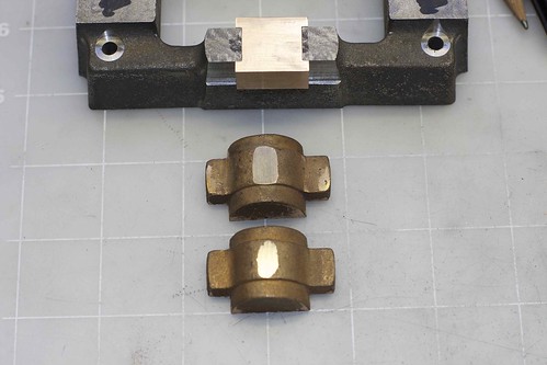
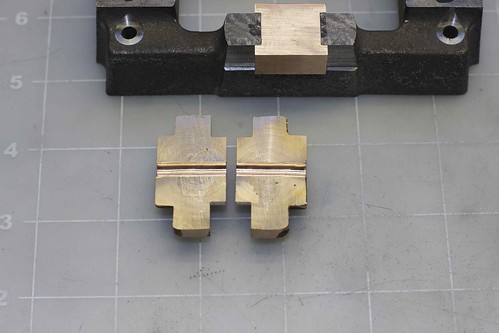
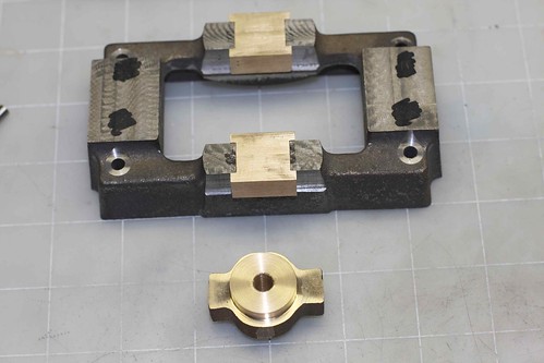
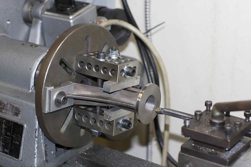
I made a couple of feet clamps:


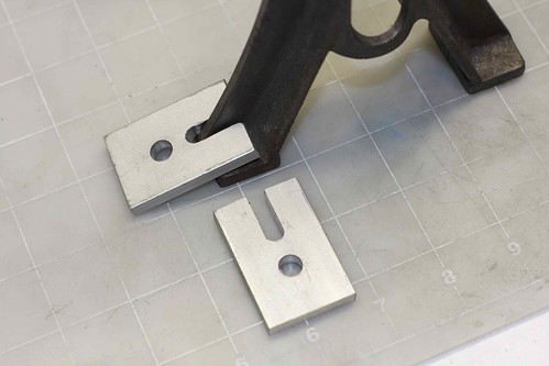
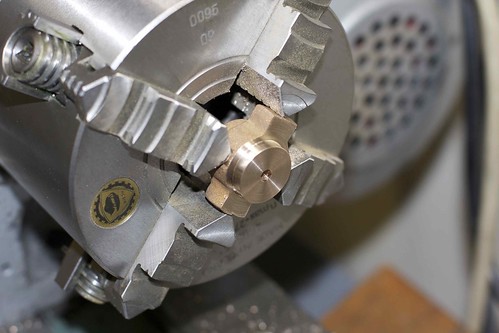
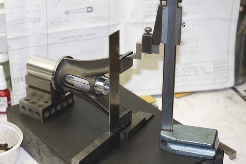
and used them to attach the standard to a faceplate. Now I used the same lap to get it mostly centered:


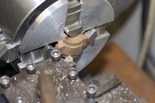
I could then take a facing cut across the top. However, when trying to take the top diameter down to size, I was getting a lot of chatter, because things weren't rigid enough, so some support with a live center in the tailstock was used which helped a lot.


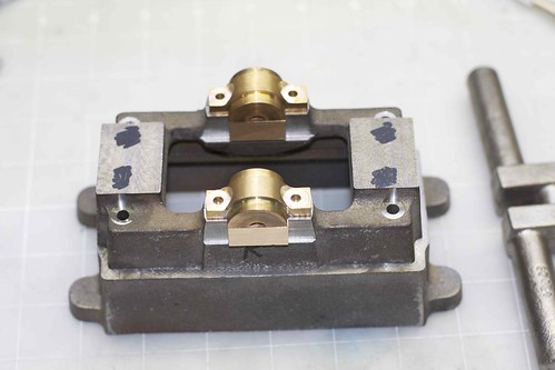
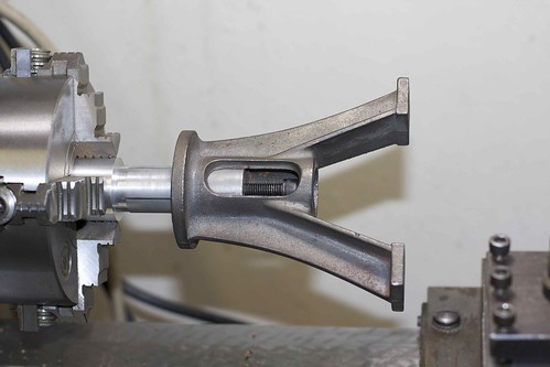
Now came the part that I was a bit nervous about: boring. I pretty soon found out that chatter was a serious issue here too, but worse because the boring bar has some flex also. I bolted some 1-2-3 blocks to the faceplate, and to each other with some Al bar spacers. This worked pretty well, once I'd adjusted things to avoid pulling the standard out of alignment.


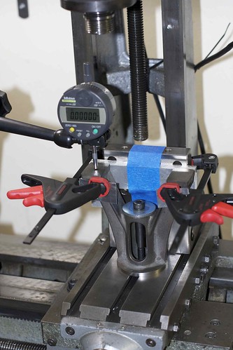
I also tried to reduce resonance in the boring bar by wrapping it in electrical tape, but that didn't seem to do much. (I suspect that chatter often results not simply from lack of rigidity, but also from the part and tools resonating or "ringing".)

The new setup worked pretty well, though the interrupted cut in the middle of the standard taught me that not all carbide inserts are created equal ;D (Yeah, I know, I should't be using carbide for an interrupted cut, but I have no HSS boring tools or inserts.)

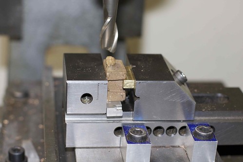
After boring to a few thou undersize, I made an Al lap:


My poorly conceived plan was to screw a pipe tap into the lap to expand it, but that didn't really work very well. Luckily the lap was tight enough at the start to still be useful.

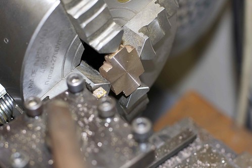
I applied the lap with a couple of grades of diamond paste:


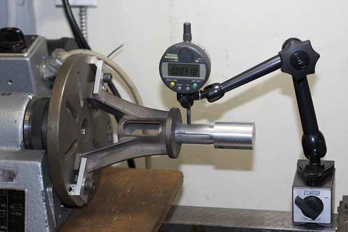
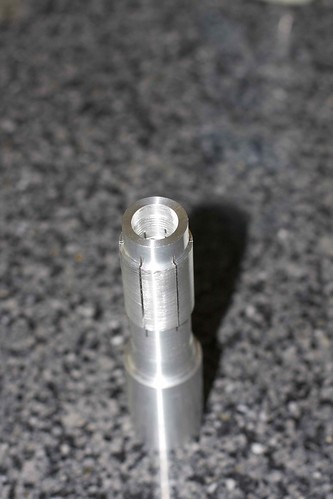
which resulted in an acceptable bore.


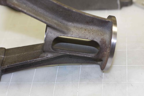
This bore is spot on 1 1/8", but I would have liked to be able to take perhaps another thou off by lapping to improve the finish. Maybe I'll figure out a way to make the lap work better and apply it again.

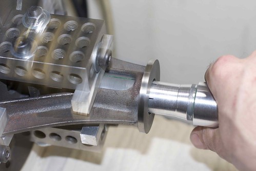
Next is to flip the standard around on the faceplate and finish off the feet to take it to final height. I'm noodling over the best way to hold the thing to keep those feet nice and rigid.

I'm also not sure if I should clean up the windows in the bore with a mill, or just leave them as-is.

Simon
 
Those feet pose a problem with a interupted cut.

I would suggest a HSS tool with some top rake and a keen edge to cut that.
Carbide doesn't like interupted cuts and you won't get the finish you want either

Keep the tool narrow and with a very small radius to prevent chipping.

Alternatively, you could use a similar set up that your used with the faceplate and 123 blocks, but on the mill and mill the feet. I personally would do it in the lathe ....with light cuts and patience.

Dave
 
Stuart models was a big reason I got interested in this hobby.
I've never made one but always wanted to.

Watching with great interest.
Great job!
 
If I were to do it in the lathe, I would make a sacraficial faceplate and clamp the cylinder flange to it. More rigid and less likely to damage.


Dave
 
Nice to see you are working on another Stuart. This one looks like a nice old casting kit from back when the casting quality was much higher nd they still included cast or forged cranks. I would imagne this one will be quite a joy to machine and build, and even more so when you aren't rebuilding someone else's mistakes. I recently got myself a very old Stuart twin launch csating kit to dig into after I've completed the Stuart triple that I'm about 60% through building. The quality of the early 1960's castings in the twin launch are amazing.

It is interesting seeing yet another perspective on how to make parts. I'm discovering that 10 different people making the same part will have at least 11 different ways to get the job done. Once the part is made, you'd never know they were each made with such different methods.

Happy building.

Robin
 
I am so glad to have join this forum. As robin has point out everyone has his own way of doing this and it just amazes me how the human mind can come up with so many unique ways. Looking good Simon I would like to build one some day,so I will be staying the coarse.

Regards Don
 
I decided to clean up the feet bottom on the mill. A bolt down through the bore was a convenient way to hold it down, and I used a heavy angle plate and some clamps just to add a bit of mass at the feet to avoid vibration:


I did quite a bit of checking with the indicator to make sure that everything was straight, since my milling table has 50 years of wear on it ;)

I took off 18thou with a sharp 1/2" end mill, and the final height is pretty close.

The flange around the feet also needs some cleanup, which I'll just do with a file, and I'm using this setup to make sure that the ends of the feet are roughly equidistant from the center line. The arbor I used to lap the bore makes a convenient holder, in a V-block. I held it down by hand while scribing the top foot, then swiveled it 180° and scribed again.


That's the standard almost done, other than drilling some holes and cleanup with files.
 
Looks like another great start on another great model! ;D

Love all the pictures of set ups used, they will come in handy one of these days!

What kind of mill do you have?
The table looks very nice!

Andrew
 

Latest posts

Back
Top