Tony Bird
Senior Member
Hi,
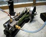
Over the last 6 months or so along with other projects I have been making a Stuart S50 horizontal mill engine for someone. It was finally finished last week and I thought members of the HMEM might like to see the photographs taken during its construction. The Stuart S50 like most of Stuarts products is machined from castings which come with all the other bits and pieces i.e. screws etc. to complete the model.
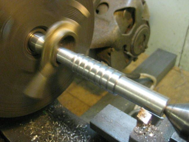
With this sort of model I usually start with the cylinders, first the cylinder casting is face on its valve surface it is the mounted in a chuck and bored and one end of it is turned a little over size. A shellac mandrel is then made a piston fit in the bore of the cylinder and the cylinder is the held on to it using shellac. The shellac mandrel is mounted between centres to finish machining the cylinder still on the mandrel the cylinder is mounted on the milling machine to mill its remaining flat faces.
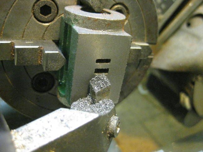
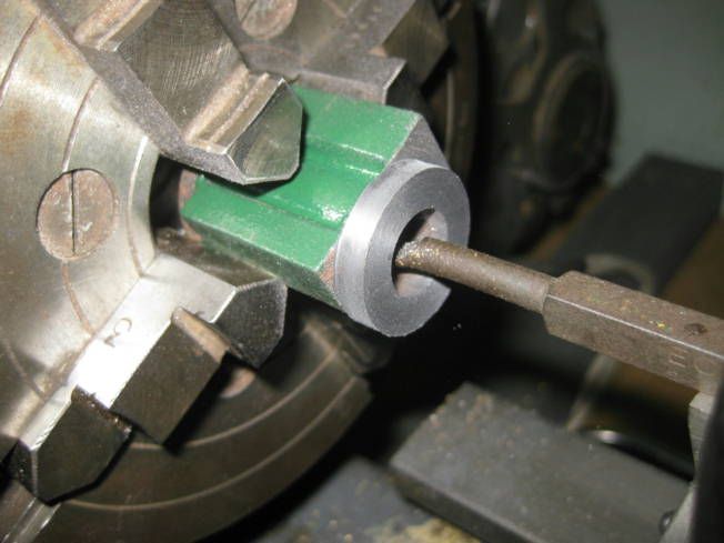
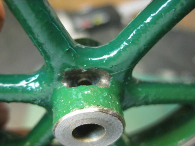
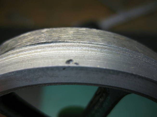
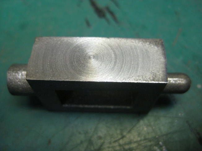
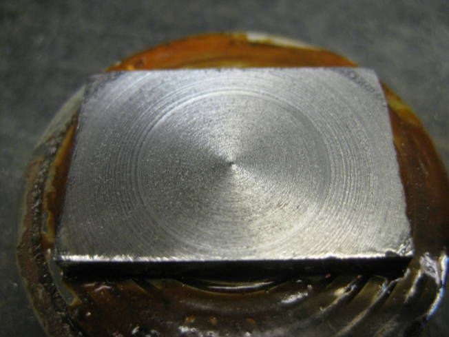
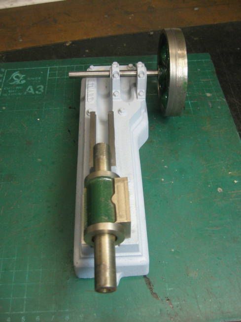
Next the flywheel was machined which was found impossible as it had been cooled to quickly it had also sagged around its boss. The steam chest and its cover were then tried and also found to be hard. But before these three casting were returned to Stuart for replacement, the engines bead was machined and drilled to see if it as well was defective. It wasnt.
While waiting for the castings the eccentric and its strap was machined along with the fly crank was machined which was straightforward.
New castings arrived, the flywheel was OK but the replacement steam chest and cover were hard. So the flywheel was machined and while waiting for the second set of steam chest castings a start was made on making and fitting the slide bars after which the connecting rod was made. It was found that the connecting rod wasnt at right angles to the axle so the flycrank had to be thinned down a bit. The crosshead was next and straightforward to make.
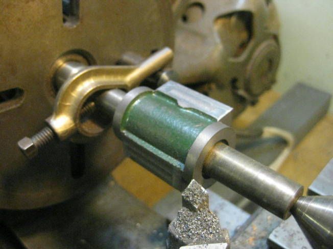
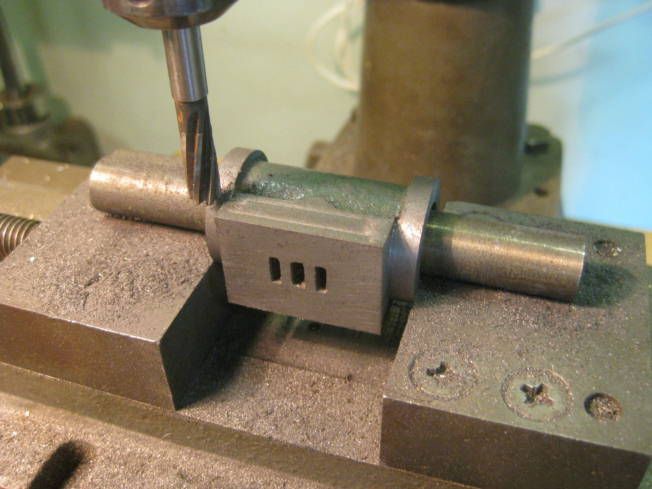
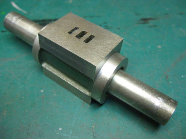
The new steam chest castings arrived and machined, they werent hard as in chilled but had some bits in them that were fortunately not enough to worry about. As can be seen from the photographs after part machining the steam chest and its cover they were stuck together using shellac to finish the machining.
Perhaps it is worth mentioning how the cylinder was lined up with the piston rod. This was a little awkward to do as three screws from under its base hold the cylinder. A shouldered plug was made for the cylinder into which an over length piston rod could slide. Doing this allowed the cylinder to be clamped to its base and it was possible to check that the piston rod hadnt stuck and could still move while the holes in the cylinder were spotted from the underside.
All of the remaining work was straightforward the only deviance from the drawings being the replacement of soft packing on the piston with an 0 ring. A Stuart adjustable Dead Leg lubricator has been fitted along with commercially made oil pots. The following photographs of which I hope it isnt considered too many shows the machining and construction techniques used. I will add the photographs in batches over the next couple of days. With luck they will be in order!
*
*
*
*
*
Chilled castings.
*
*
*
Base checked before castings returned.
I'll stop now and do some more later.
Regards Tony.
Over the last 6 months or so along with other projects I have been making a Stuart S50 horizontal mill engine for someone. It was finally finished last week and I thought members of the HMEM might like to see the photographs taken during its construction. The Stuart S50 like most of Stuarts products is machined from castings which come with all the other bits and pieces i.e. screws etc. to complete the model.
With this sort of model I usually start with the cylinders, first the cylinder casting is face on its valve surface it is the mounted in a chuck and bored and one end of it is turned a little over size. A shellac mandrel is then made a piston fit in the bore of the cylinder and the cylinder is the held on to it using shellac. The shellac mandrel is mounted between centres to finish machining the cylinder still on the mandrel the cylinder is mounted on the milling machine to mill its remaining flat faces.
Next the flywheel was machined which was found impossible as it had been cooled to quickly it had also sagged around its boss. The steam chest and its cover were then tried and also found to be hard. But before these three casting were returned to Stuart for replacement, the engines bead was machined and drilled to see if it as well was defective. It wasnt.
While waiting for the castings the eccentric and its strap was machined along with the fly crank was machined which was straightforward.
New castings arrived, the flywheel was OK but the replacement steam chest and cover were hard. So the flywheel was machined and while waiting for the second set of steam chest castings a start was made on making and fitting the slide bars after which the connecting rod was made. It was found that the connecting rod wasnt at right angles to the axle so the flycrank had to be thinned down a bit. The crosshead was next and straightforward to make.
The new steam chest castings arrived and machined, they werent hard as in chilled but had some bits in them that were fortunately not enough to worry about. As can be seen from the photographs after part machining the steam chest and its cover they were stuck together using shellac to finish the machining.
Perhaps it is worth mentioning how the cylinder was lined up with the piston rod. This was a little awkward to do as three screws from under its base hold the cylinder. A shouldered plug was made for the cylinder into which an over length piston rod could slide. Doing this allowed the cylinder to be clamped to its base and it was possible to check that the piston rod hadnt stuck and could still move while the holes in the cylinder were spotted from the underside.
All of the remaining work was straightforward the only deviance from the drawings being the replacement of soft packing on the piston with an 0 ring. A Stuart adjustable Dead Leg lubricator has been fitted along with commercially made oil pots. The following photographs of which I hope it isnt considered too many shows the machining and construction techniques used. I will add the photographs in batches over the next couple of days. With luck they will be in order!

*

*

*

*

*

Chilled castings.

*

*

*

Base checked before castings returned.

I'll stop now and do some more later.
Regards Tony.