Stirling displacer, copper end thoughts

Home Model Engine Machinist Forum

Help Support Home Model Engine Machinist Forum:

This site may earn a commission from merchant affiliate links, including eBay, Amazon, and others.

ghart3

Well-Known Member
Joined
Feb 12, 2008
Messages
154
Reaction score
1
Working on a Stirling hot air engine.

Making a displacer out of .018" thick stainless steel rolled into a tube. Diameter about 2.5" and about 10" long.

If the hot end of the displacer had a silver brazed on copper end about 1/8 thick would it be a good or bad idea?

Thinking it would make for quicker heating of the air at the hot end.
 
You want to make the displacer as light as possible copper would be on then heavier side not sure that would be a good idea.
 
I suspect that might just heat the entire displacer, which might not be for the best. If you could insulate behind it, it might act as sort of a regenerator.

FWIW, I remade my Ridders Egg Cup Stirlings with copper-clad circuit board displacer disks (thin copper on either side of a bit of fiberglass) and they seemed to do at least as well as the original Lexan ones that got droopy due to heat.

 
Good point. Could make copper say about .030 or .040" thick with grooves for more surface area?
 
I'm not sure what gain you would get from a copper end on the displacer itself. It's purpose is really to just displace air inside the cylinder, although some designs have it doing double duty as a regenerator, I think.

If the displacer is airtight, the heating of the air inside it could cause it to bulge if enough pressure built up. The material you are using is fairly heavy though.

I had thought about changing to a copper hot cap on one of mine, just to see if it makes a difference in the amount of heat it takes to run. It currently has an aluminum displacer and a steel hot cap.

I have another design that uses a copper cap on the displacer cylinder with the cylinder itself being steel. Haven't got around to building it though.

Kevin
 
Sorry to resurrect an old thread, I'm new here, but this fits in with an idea I've been toying with.

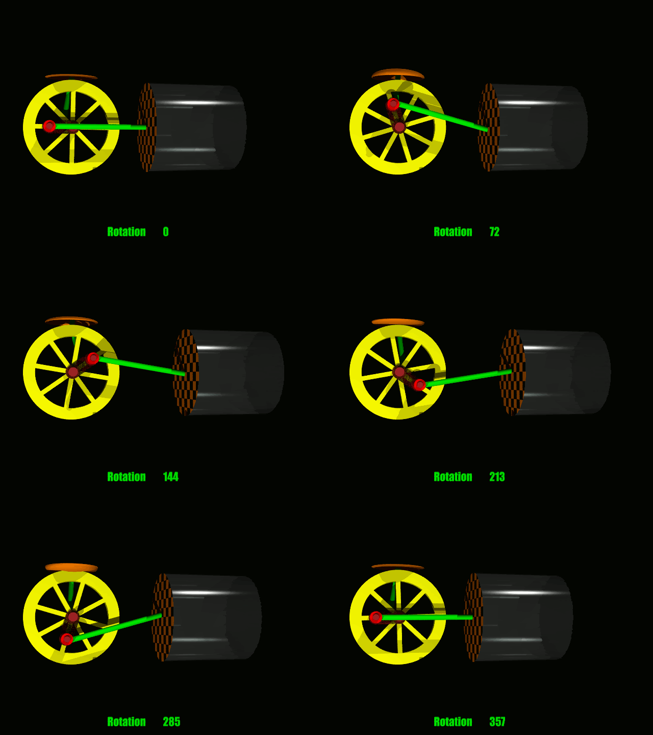
My idea is to make the displacer itself a hot air chamber within the stirling, though that may not be the best description. The concept is to have the displacer bottom out (thinking anywhere from 5-15 degrees before BDC), with a heat exchange type material on the hot end, and a diaphragm on the cold end.

As the displacer aproaches BDC, it comes in contact with the hot cylinder base wall. This begins to heat the air inside the displacer. As the motion continues past BDC, the air will have heated enough to give a push to the con-rod as it passes BDC. Residual heat from the hot end of the displacer is then used by the air (not a regenerator, but instead uses more of the heat during a time in the phase when heat is normally blocked).

Would love to hear some thoughts on this, and I can post an animation if needed.
 
Hi Jerry Script
I have seen an idea where the hot end has lots of rods going into the hot end but never actually touching it, the idea being to increase surface area and hence better heat transfer.

With your idea for the displacer to bottom out, does this mean you won't have a sine wave motion? I know the ideal motion is a square wave form but surely this could only be achieved on a very slow running engine?

I think I understand your idea about heat transfering to the displacer to give 'a second dose' of heat for the expansion stroke? I'm not sure the engine will have time to cool the air if the hot phase is extended. With only 90 degrees out of phase will it have room/ time to expand the hot air after the second dose of hot air?

Just a few thoughts while opening ceremony is on.

Kevin
Jersey
 
Thanks for your thoughts on this Kevin.

The "perfect stirling cycle" actually does keep both the displacer and power pistons bottomed out longer than the "standard stirling cycle." However, very few working engines have ever been built to use a "perfect cycle." Several animations of various gear/cam systems can be found on google that attempt to create the "perfect cycle."

The displacer will bottom out when the displacer crank is about 10 degrees before Bottom Dead Center. The diaphragm on the cold end of the displacer being attached to the con rod will become slightly in-pressed. As the crank rounds BDC, the heat build up in the displacer should then force the diaphragm out, pushing on the con-rod rather than relying on only flywheel momentum. Once the displacer crank is about 10-15 degrees past BDC, the displacer will move away from contact with the displacer chamber, with the resulting heat build up then tranfering to the cylinder air, increasing the amount of energy in the system. Proper cooling on the cold end will need to take into account this extra energy, perhaps with a redesign of the 1/3-1/3-1/3 hot-regenerator-cold dimensions, increasing the cold area (which just happens to fit perfectly with another aspect of my design, but that's for another thread). I will put an animation together this weekend to show my concept better.

Edit: threw a quick animation together, I messed up the con-rod connecting point, but it shows the concept:
power-displacer-stirling.gif
 

Latest posts

Back
Top