Stephenson's Rocket--Working Model

Home Model Engine Machinist Forum

Help Support Home Model Engine Machinist Forum:

This site may earn a commission from merchant affiliate links, including eBay, Amazon, and others.
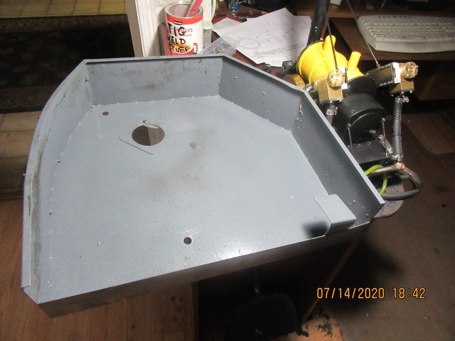
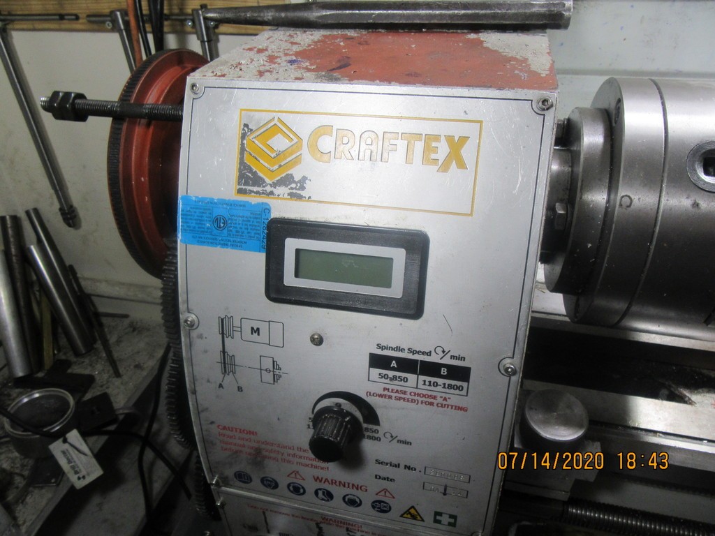
This is what was wrong with my lathe One picture is of the gear cover that sets on the end of my lathe to protect my fingers from the gears. Notice the bent bracket at the lower right corner of it. That bent bracket pushes on a switch which disables the electrics on the lathe if the guard is removed. I haven't had that cover off the lathe in more than a year. Somehow---Perhaps metal fatigue? the bracket bent far enough that it no longer pushed on the button, and consequently the lathe stopped right in the middle of a cut. The switch it presses on is right below the gears and is virtually impossible to see unless you stand on your head to look for it. When I left the lathe in Concord at Busy Bee, I told them that my rpm indicator only worked intermittently and please either fix it or replace it, as well as please fix whatever is wrong that I have no power to the lathe. They replaced the rpm indicator, scratched their heads a bit and then found that bending the bracket by hand fixed things so it pushed the button and restored power to the lathe. I either didn't know, or else forgot that switch was even there.They charged two hours labor and the price of the new readout. My bill came to $129. So, they treated me quite honestly I think. They could have told me it needed a new motor and charged me another couple of hundred dollars but they didn't.
Y6Ip0a.jpg

HqxmBG.jpg
 
Today I worked on the series of manifolds necessary to get air into the cylinders. This was one of the areas that wasn't pre-engineered. I wanted the airline to be attached at the back of the Rocket, under the center of where the operator stands. Since this part of the build was a "make it up as you go along" operation, it required that the operators platform and fire-box and rear stay rods had to be removed from the model to be worked on. First, I drilled and reamed a 7/8" hole completely thru the firebox. Then I made up a 7/8" length of aluminum which fit flush from side to side. A 3/16" diameter hole was drilled full length thru this piece, and each end was counterbored for an o-ring seal, and drilled/tapped for four #4-40 socket head cap screws. A hole was cross drilled half way thru the piece on center, and threaded 3/8"-16. The piece now obscured the 1/4"-20 thread for the bolt which holds the fire-box cover in place, but with some artful head scratching and measuring, a #10-24 hole was drilled and tapped in the appropriate position to accept a #10-24 shcs. While I had everything set up in the mill to cut the 7/8" diameter holes, I also drilled and tapped one side of the fire-box for a #8-32 set screw to anchor the 7/8" aluminum round bar in position. Also, I drilled a 13/32" clearance hole up thru the operators platform and thru the bottom of the fire-box. This allowed me to use a 3/8" diameter piece of steel, threaded on one end , to screw into the threaded hole in the 7/8" cross-piece. I also drilled a 1/4" clearance hole thru the rear axle bracket, which allowed me to install a piece of 1/4" diameter steel round bar thru the bracket and into a hole prepared in the 3/8" piece of steel. Some of these holes were much easier to drill in the manifolds from each end, so after I had made a trial assembly to be sure everything fit, I liberally coated all of the connections with J.B.Weld and screwed/pushed everything together and inserted steel plugs into the open ends where I didn't want air to escape. The metal tubes which extend downward from the valve boxes on the cylinders will have a flange on the bottoms which bolt to the ends of the 7/8' round aluminum. Damn, it takes almost as long to explain what I did as it did to do it. Last job of the day was to update the drawing package and add these new parts to the assemblies and make detail drawings of them.
i9zKAO.jpg

Y8yrIZ.jpg
 
Barry, love looking at your work, you are so productive with such great results!!! Not sure I will ever make a version of your Rocket, but would sure love to.

I would like to ask you where you obtain your brass and bronze, I find that difficult unless I am looking for fairly large amounts.

Colin, Burlington Ontario
 
Colin--First of all, my name is Brian, not Barry.---Secondly, I buy all of my material locally at A to Z Metals or at Metal Supermarket or at Barrie welding, all located here in Barrie.
 
Today, I have had my butt thoroughly and awesomely kicked by Mr. Stephenson. The goal was to get set up for fabricating the air pressure lines feeding the steam-chests. This picture shows where I am ultimately going. It has been a worrisome and eventful day, but I have one side set up. The bent copper tube gets silver soldered to the flange. It is a "slip fit" over the barb hanging down from the steam-chest cover, and will be sealed tight with J.B. Weld.---At least that is the plan at the moment. If I'm really forced to, I can use a flexible nylon line there, but I don't really want to. By the time I'm done here, I'm going to have to repaint the fire box.
Xh4bl0.jpg
 
I really have to try and find a model "driver". I need a little man 5 1/2" to 6" tall to stand on the platform. I haven't got around to checking any of the toy stores yet.
 
Jigs and fixtures---Fixtures and jigs. Some of the jigs I make are based on pure mathematical calculations. Some are "best guess". This one is a combination of both. If I have lived right, this may be the last on this engine. This is one of the times where I have had to tell myself "Try it and see if it works". You will see that the silver solder has joined the bent tube and the flange, but has also wandered over and attached the socket head cap-screws. I expected this. Thats why there are only two capscrews holding each flange in place on the fixture. I will mill the heads off of the capscrews and cut away the angle which forms the welding jig, to free up the parts.
q1q2gJ.jpg
 
Brian, i have heard but not tried liquid paper or white out will prevent silver solder from sticking to parts you dont want stuck. didnt know if you had ever tried that or not. not much help now of course but just wanted to share what i had heard incase it might help in the future.
 
Werowance--I have been using that trick for many years.--It does work---sort of. Where there is lots of room, it will prevent solder from flowing where it is applied. When the entire weld area is almost the same size and there are a number of pieces involved, the liquid paper burns away and doesn't work.
 
So--How did it work? it worked out perfect!!! Both welded pieces slid into place on the engine. I had used a bit of crazy glue to secure rubber o-rings into the ends of the 7/8" diameter manifold that ran thru the fire box. I coated the short tubes which were welded to the steamchest covers with J.B. Weld, and slid the welded pipes with flanges into place with no trouble. The flanges lined up, and the bolt holes in the flanges lined up. I tightened the flange bolts on one of the tubes, and felt it suck down into place as the rubber o-ring compressed. Went to tighten the bolts thru the other flange, and noticed that the flange wasn't setting as flush as I would have liked with the side of the fire box. I thought "Oh well, the copper tube will flex enough to let me tighten the bolts".---Hah!!!--The copper tube didn't flex at all. The silver soldered joint let go on one side. Ah Poop!!! To get really good secure joints with J.B. Weld, it shouldn't be disturbed for 24 hours after mixing. That was okay. I had a small patent drawing to prepare for an inventor, so I spent this afternoon doing some honest design work while the one good silver soldered pipe was setting up. Tomorrow I will undo the broken/silver soldered tube and flange and resolder it. After reassembly, assuming all goes well, I will hand paint the tubes to match the fire box.
436wHA.jpg
 
So--How do you silver solder one end of a tube without melting or burning out the J.B.Weld on the other end? You wrap the end with the J.B. Weld in a piece of cloth, tie it with some string to prevent it from sagging away from the tube, then soak the rag in water. As long as you don't spend too much time silver soldering the other end, the wet rag prevents any heat transfer into the other end of the tube.
thAse7.jpg
Brian, what is the track width of your model and how much work do you think it would be to modify to suit a 4-3/4" track? What format are the drawings you are offering to sell, my SW is a 2006 version so if you are using a more recent version would be interested in IGS or step.

Colin
 
After some re-soldering, re-assembly, and some touch up painting, we arrive at time for the final? "Beauty Shot" and the video. I still hope to find a period dressed driver to mount on the drivers platform, and I hope I can make a video of it running on it's own power across my office floor.
1h8puq.jpg

 
Lampapabear--Measured inside the flanges on my wheels is 4.7". That would be the inside to inside dimension on rails for it to run on. It would actually take very little to change it to suit a 4 3/4" track. I will sell the drawings as .pdf files and include the solid models as .step files for $40 Canadian funds. I normally charge only $25 Canadian for my engine drawings, but this build is far more extensive than any engines I have designed and built.---Brian
 
Back
Top