Stephenson's Rocket--Working Model

Home Model Engine Machinist Forum

Help Support Home Model Engine Machinist Forum:

This site may earn a commission from merchant affiliate links, including eBay, Amazon, and others.
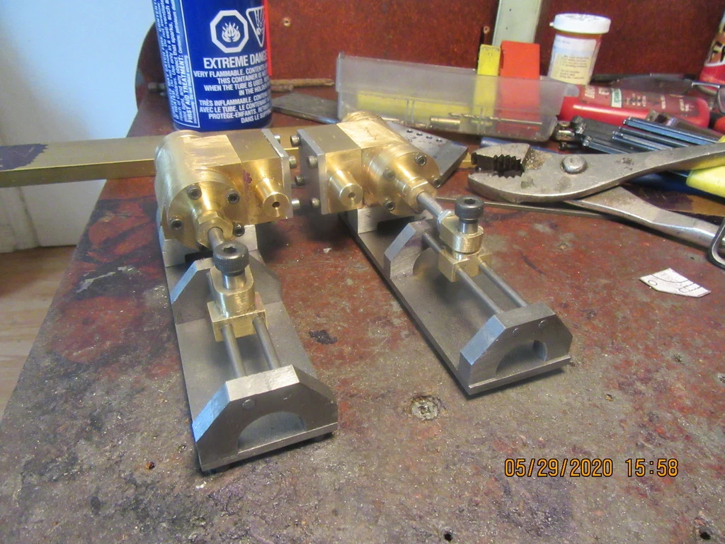
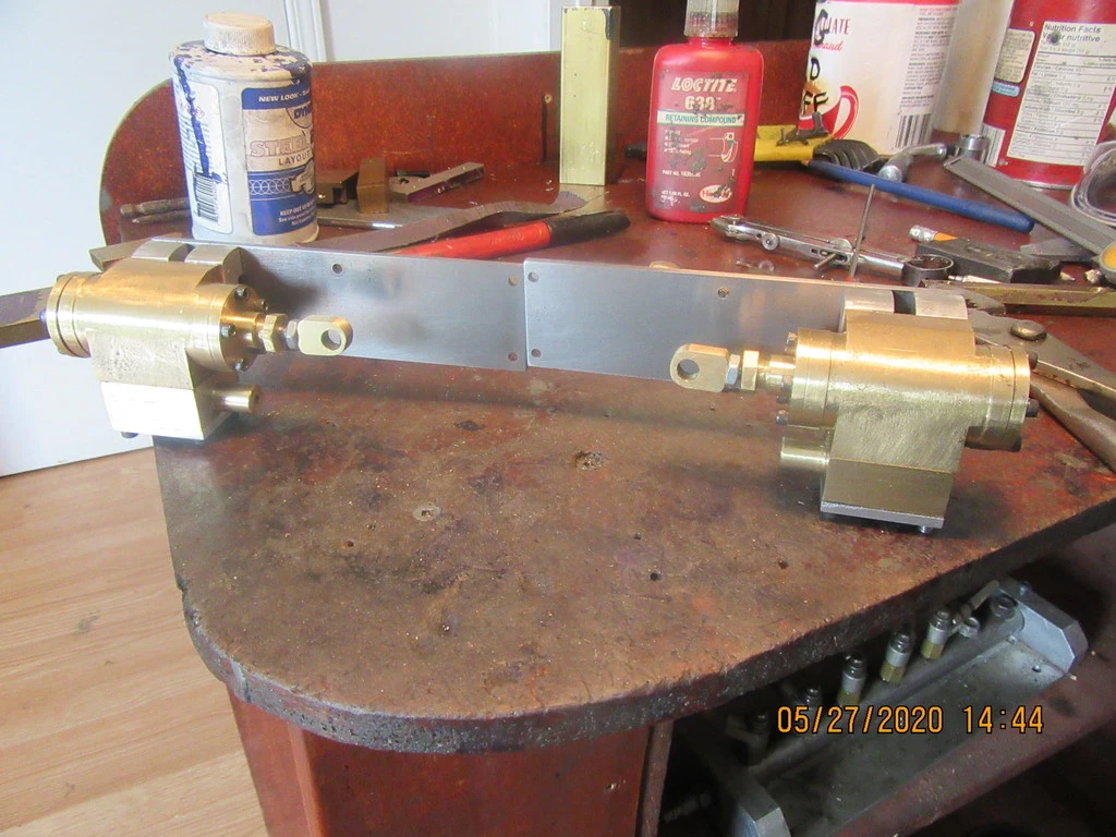
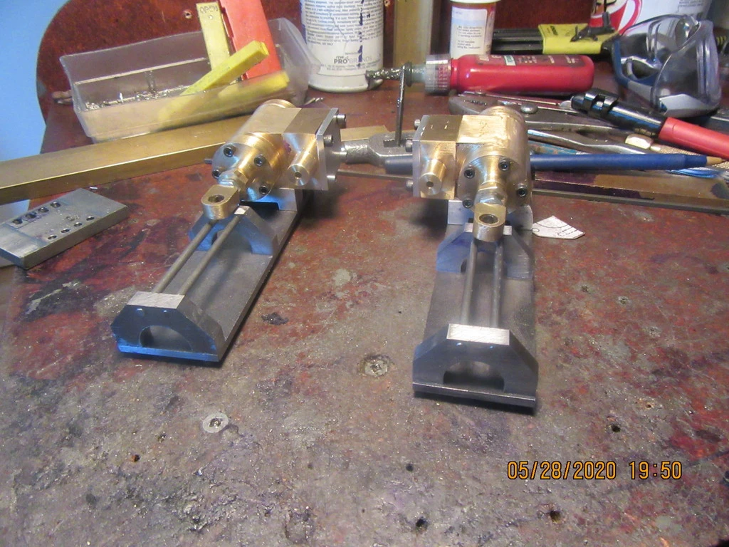
I have a reamed hole in the cylinder end cap for rod guidance. The bore of the screw in gland is 0.015" larger--it doesn't really provide guidance, it just holds the packing in place around the shaft. I make the packing from teflon tape for plumbing work rolled into a small diameter, rope by twirling it between my thumb and finger.
 
I had the very best intentions today, of building the four brackets which support the cylinders. However, "The best layed plans of mice and men Gang aft agley"---I did get the four pieces cut to size, and I actually did drill and tap four holes and add two counterbores and a bit of end profiling on one piece and got it mounted. That's not much to show for the day, but I promise---I'll get the other three finished tomorrow. Good wife and I were setting out on the back deck about 4:20 this afternoon having a vodka cooler, when suddenly it began to rain so hard we couldn't see the end of our yard and the wind was blowing so hard that my big oak trees were leaning almost horizontal. We quickly scurried inside and the wife wanted to know if we should head for the basement--She's been through a tornado before---I haven't. I said to wait for a minute and see what happens. Five minutes later the sun was shining again. Crazy, crazy day!!!
kaprf0.jpg
 
So, as promised yesterday, today the aluminum feet were finished and bolted in place. The main baseplates for the right and left hand cylinder assemblies were cut to size and drilled to allow mounting of the cylinder assemblies. Tomorrow I will probably make the A shaped pieces that support the cross-head guides. I haven't cut the windows into the baseplates yet. Initially everything will be assembled "for fit" before I cut the windows.
r1KfHj.jpg
 
Today was the day for cross-head guides and brackets. I don't really know why, but I had a horrible time with these brackets. I kept taking off a little bit here, and a little bit there, and by the time they all matched and looked right, I had almost used up my entire day. The 1/8" cold rolled steel guides themselves were easy enough, but the brackets almost kicked my butt!!
R9IhNI.jpg
 
It's a hobby - the way I look at it, the longer it takes, the more effective it is at being a hobby.
When I occasionally spend £50 on a lump of aluminium and my wife raises an eyebrow, I need only refer her to golf club membership fees to demonstrate that this is a cheap hobby.
Some of the apparently simple parts can easily take up a disproportionate amount of time. I spent several hours yesterday cutting out stainless sheet parts which will become exhaust clamps - and I've only done half of them.

And Brian - your Loctite has fallen over... :)
 
Today was cross-head day. I would rather run in circles and bite myself than make pieces this small, but these are probably the smallest parts of this build, and they turned out alright. Don't let the size of these parts fool you. To get them to slide freely on the cross head guides and not jamb up the cylinder over the full extent of it's stroke is almost a magic act. As you can see from the picture, I changed the design of the cross-head a little bit from my original plan which both made it simpler to build and let me use a store-bought shoulder bolt as the pivot. The round cross-head guides are silver soldered to the bracket closest to the cylinder. At the end farthest away from the cylinder they are just setting in reamed holes, which positions them accurately but lets me disassemble them if I need to.
R9SZoY.jpg
 
Today was mostly given over to the sliding valves for each cylinder. They are finished and look all right, but I won't really know until I get my gaskets cut and installed and some air pressure to work with. I have been wondering for the last week how I was going to get air pressure into the rectangular "steam chest" that the slide valves set in. I decided today to scrap the aluminum steamchest covers that I made and replace them with mild steel. This will let me silver solder an air inlet tube to the center of each cover. The pressure doesn't care how it gets into the steamchest, as long as it gets in.
kHWOt1.jpg
 
Today was a minor milestone. I just finished making the gaskets for one of the two cylinders on this engine, and of course I wanted to see if /how it worked. I always get a little thrill out of reaching a point where the slide valve controls the movement of the cylinder.
 
Some days you eat the bear---Some days the bear eats you!! I spent an absolutely insane amount of time today freeing up the cross head to slide smoothly with the extension and retraction of the cylinder. I got one unit finished. I can extend or retract the cylinder by shifting the slide valve and watching it smoothly do it's business.The other cylinder though, is being a beast and binding like crazy---and the slide valve isn't seating correctly against the side of the cylinder. If I can hear air hissing, then the slide valve isn't seating properly. I will fix the second unit tomorrow---and ---guess what?--I can't really do any more until I build the test stand to mount the cylinders and cross heads and baseplate to. After I get the test stand built, I will move on to the eccentrics and connecting rods.
H10L4b.jpg
 
I spent far too much of today getting the cylinder assemblies to extend and retract when connected to the cross-head guides. In all honesty, I don't think I would recommend this style of cross head guide system. With the offset between the cylinder rod and the two cross-head guide rods, there is simply too much binding. I ended up having to o-ring one piston. My intent here was to use no o-rings, just a couple of oil retention grooves in the pistons. The best cross-head guide system I have seen is the one used on the Cretors Popcorn engine, where there is no offset involved. By the end of the day I had both cylinders extending and retracting while attached to the cross-head guides, but it was a hard fought battle.
 
Brian, Congratulations on getting everything moving. The system is fandamentally over-constrained and I wouldn't be surprised if it were to give you more problems later on - I can imagine that any load or thermal expansion could cause a small misalignment and binding.
If I might make a suggestion... the purpose of the crosshead is to carry the bending load exerted by the connecting rod, so that it is not expressed at the piston rod. The piston rod end at the crosshead could afford to have some clearance, both along the shoulder bolt axis and perpendicular to the crosshead rails by opening up the shoulder bolt hole to a slot, with just a few thou clearance either side.
 
Went across town to see my metal supplier and picked up a 1" thick offcut for $5.00 this afternoon. Brought it home and added it to the flat bar which supports the cylinders. I wear a mask my wife made from black cloth material, and every time I see myself in the mirror I think of the Lone Ranger. ---or some other masked desperado. Damn, I hate this covid stuff.
gpqQUn.jpg
 
More like the lone stranger. Every time I look in the mirror I want to know who this woolly individual is. Beginning to look like saskwatch or however you spell it. Isn't Ontario isolation wonderful. RonW
 
The engine test stand is almost complete. About 95% of this stuff is "Pre-engineered" in my 3D cad work.--The other 5% is "make it up as I go along", then go back and update the model and drawings to reflect what I have really done. I have to make up a baseplate to add to the bottom of this stand, and then I'm about ready to begin all of the small pieces which are required to get power to that front "axle". You will notice that the front axle support has a weird shape. It is actually the drive axle support which goes on the train body itself, I just haven't cut the arc yet where it bolts to the underside of the boiler.
OFWxhf.jpg
 
The hole that my front axle sets in was drilled and then reamed to 3/8". When I put the axle in the hole, it was a terribly sloppy fit. I couldn't figure out why my reamer had cut oversize---it never did before. A closer examination this morning showed that I've been METRICED---the 3/8" reamer I had used was a 10 mm reamer, which is 0.394". Don't know what fool put the metric reamer into the 3/8" reamer stand!!! Then I went to make the eccentrics which attach to the axle, and totally buggered them up. At that point I shut things down and took my good wife out for lunch, then had a walk and an ice cream cone. Now I will take another run at those eccentrics.---
 
I will gauge my day by what happens in the first fifteen minutes. I have had days where every single thing went as smooth as silk, and I spent 10 good hours getting a huge amount of work done. And I have had days where I broke a drill off in the first 5 minutes, mis-tapped a hole because the tap was in the wrong little plastic case, and then stopped and thought about it, and just went off to go see a movie and have a nice lunch. (I take my project plans with me, and sit and peruse them (Sometimes I gaze at them, or even OGGLE them!) while I eat.
No point in beating a dead horse. Or propping him up with sticks and trying to keep him from falling over. Just do something else.
 

Latest posts

Back
Top