Steam valve Diagrams

Home Model Engine Machinist Forum

Help Support Home Model Engine Machinist Forum:

This site may earn a commission from merchant affiliate links, including eBay, Amazon, and others.

Dan Rowe

Well-Known Member
Joined
Feb 12, 2010
Messages
594
Reaction score
18
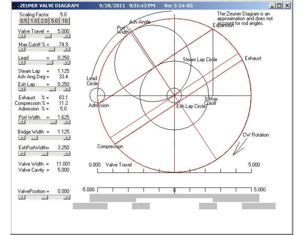
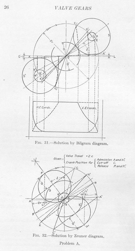
I think the three most common steam valve diagrams were Zeuner, Reuleaux, and Bilgram in that order. I will show how to construct each one.

The grandaddy of all of these is of course Zeuner so lets start there. I have a copy of Treatise on Valve-Gears by Dr. Gustav Zeuner but it is mostly Greek in the form of algebraic notation. It is well beyond my comfort level with mathematics.

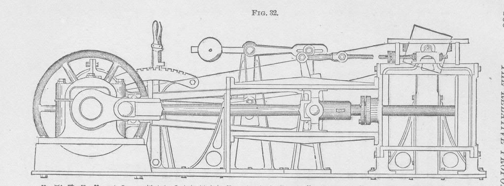
I did find a drawing of the machine made at the University of Pennsylvinia used as a drafting instrument to construct Zeuner Diagrams. It was made to the same dimensions listed in Zeuner's book. It is very clever. It is a cut away engine much like a valve gear trainer but a drafting board is mounted on a spindle near the valve. Thie board is made to rotate at engine speed and a pencil is attached to the center of the valve. The curves generated on the board is what Zeuner used complex math on to replicate with his diagram. Now really how cool is that?

Zeuner001.jpg


The next post I will use one of my favorite authors William Ripper to loft a Zeuner Diagram for a two cylinder launch found in Machine Drawing and Design.


Dan
 
Peter, Thanks for the interest. I used the book as it was intended as a drawing exercise. I often draw the diagrams in valve gear books in my study of the old graphical methods. To see a two cylinder 7"x7" launch engine found in the same book: http://www.gouldstudios.com/me_SteamLaunch.html

Here is the valve and the set of start assumptions for a Zeuner diagram found in Ripper's book.

ZeunerRippervalveHMEM.jpg


Here is the procedure I used to draw the Zeuner Daigram for the valve.
ZeunerRipperHMEM2.jpg

ZeunerRipperHMEM3.jpg

ZeunerRipperHMEM4-1.jpg

ZeunerRipperHMEM5.jpg


Here is the full diagram with the exhaust port width and more modern terms than Ripper used. I also indicated both TDC and BDC as I usually draw these vertically because I think pistons go up and down.

ZeunerRipperHMEM6.jpg


Finally here is a screen shot of the valve entered in Dockstader's Zeuner module. Notice it is a mirror image because the rotation is the other way.
ZeunerRipper.jpg


I just noticed that the last diagram from my original drawing has 3/8" lead not 1/4" as Ripper stated. I got it wrong on my first try but it shows the effect of changing the lead. It is much quicker with the computer program to see the changes.

Valve diagrams really can be used for two uses. One is to solve a valve gear problem the other is to compare one valve design with another at a glance. It is the second use that I use Zeuner for because a lot of text books use a Zeuner Diagram to illustrate the authors points.


Dan
 
Dan,

Thank you :bow: I am looking forward to the other ones.

Best Regards
Bob
 
The next one up is the Reuleaux Diagram. I have not made many of these but I have always thought it is a very interesting method.

Franz Reuleaux is considered the father of kinematics and invented a lot of very interesting stuff including the Reuleaux triangle which was used in the Wankel engine. Can some classically educated person tell me how to pronounce the mans name? I always feel like a hillbilly when I attempt saying it.
http://en.wikipedia.org/wiki/Franz_Reuleaux

I will use the same valve as before and use the method found in The Constructor by Franz Reuleaux. This method needs the length of the connecting rod so I will use the rod length found in Ripper's book.

Dan
 
I am going to hazard a guess that it is something like "Ray-loo", but don't quote me on that.

Pat J
 
Boy,am I dumb!!!!! :wall: :shrug: *club*
 
Interestingly, Reuleaux was German, not French. My French is far from good but, like Kvom, I would pronounce it Roo-low.
 
Thanks for the help on the way to say Reuleaux, I was not even close as I knew that he was German and that made me think the x was not silent.

I will get back to the diagram in The Constructor it is a more complex version that uses the connecting rod length.

This is the simple version. I took a look at Model Engineers Handbook by Tubal Cain and I modified that diagram to match the rotation shown with the Zeuner diagram.

The hard bit for me to figure was the angle of advance if it was not given in a drawing set. Well thanks to this thread I have finally worked that out in my head. The angle of advance is the angle the the eccentric is ahead of the crank plus 900.

Looking at the Zeuner diagram it can be seen that the sine of the angle of advance is the opposite divided by the hypotenuse or the
(lap + lead)/(1/2 valve travel) = sine of the angle of advance.

This was the part I was hanging up on but it is the calculation required with the start information we have for all the diagrams.

Now you will notice that the simple Reuleaux diagram is exactly the same as a Zeuner diagram it is just a quicker way to draw it.

ReuleauxRipperHMEM.jpg

Reuleaux1RipperHMEM.jpg


I imported the Dockstader Zeuner diagram into my cad program. Then I made a red mirror image the Reuleaux diagram in the last post and centered it on the image.


ZeunerRipperDockstaderHMEM.jpg


Now it should be clear how the graphics work in Dockstader Zeuner module. I still have to explain some of the output numbers and the port width line.


Dan
 
Dan-

Nice diagrams.

I still have trouble with the polar plots, and I keep hoping that a light will turn on in my head one day like it did with learning to use Solidworks.

I am going to dig out a few other programs written by others and try and review them and compare.

Sure would be nice to have a standard set of published formulas and variable definitions for steam engine design. I think you have looked at this before and have run the same calculations in multiple programs, so that is a good thing.

Now we just need one universal program that is documented.

Pat J
 
Pat,
I had a similar reaction to polar plots and steam engines. Funny they work fine for IC engines in both the timing diagram form and the firing order form but thinking about steam engines that way was a stumbling block for me also.

The real difference with a steam engine is it is double acting engine and that makes the diagram complicated. Not many IC engines have been built that are double acting. It was tried with diesels in the 1930's but the rod seal was problematic with the higher gas pressures.

Some authors like H. W. Spangler Professor Mechanical Engineering University of Pennsylvania recommended making a separate drawing for both ends of the cylinder. Here is his figure 12 and 13 from Valve Gears 1900.
He uses left end and right end for the two sides of the piston which is a bit confusing. I think that head end and crank end are more helpful to the reader. I do like the book because he is consistant through the book with variables and gives a key in the first of the book more like a modern engineering text.

Spangler_fig12001.jpg

Spangler_fig13001.jpg


The other approach is to put both ends on the same diagram.This is how Charles Fessenden Professor of Mechanical Engineering University of Michigan worked a sample problens with a Zeuner diagram in Valve Gears 1915.

Fessenden001.jpg


The upper figure is both ends of the engine using a Bilgram drawing. The lower figure is both ends of the same engine using a Zeuner diagram. I think that clearly makes the point I want to make that it is much simpler to see what is going on with both ends of the cylinder with a Bilgram diagram. Notice also that the graphic also shows a simplified indicator diagram under the Bilgram diagram. I think this was done just to show engineers who were very familiar with indicator cards and diagrams what was happening in the diagram. The next sample problem has a similar page only the indicator card graphic is below the Zeuner diagram not the Bilgram diagram.

Next up how to construct a Bilgram diagram.

Dan
 
I like the separate drawings for each end of the cylinder, that would seem to make it easier to understand.

Sometimes the plots seem to get overloaded with information, which is ok I guess if you understand it.

Simple works better for me, and the more simple the better as far as I am concerned.

Pat J
 
I am sad to to report that Charlie Dockstader has passed away.

He will be missed by many folks like myself that never met him but have spent many hours using the programs he wrote for the live steam comunity.

Dan
 
Dan-

Sorry to hear that.

I pushed him hard to open source his programming code so that others could continue his work.

He actually send me a copy of his Pascal code for the Stephenson's link.

It is very tedious stuff, and no documentation in it of any kind, but I can see what he is doing with it, and it was exceptionally nice of him to send me that.

I hope to recreate his programs in a more modern programming language such as "C", and publish it as shareware, with documentation.

Pat J
 

Latest posts

Back
Top