Steam Raising Blowers - a comparison

Home Model Engine Machinist Forum

Help Support Home Model Engine Machinist Forum:

This site may earn a commission from merchant affiliate links, including eBay, Amazon, and others.

glue-itcom

Well-Known Member
Joined
Apr 10, 2013
Messages
216
Reaction score
298
I made an electric fan with a homemade aluminium centrifugal fan blade. I then made a simple u-bend hockey-stick pipe and fed compressed air into it.

I compared both of these methods for raising steam in my small vertical boiler.

raising-blower-09.jpg

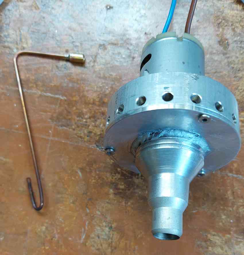
on the left is the compressed air hockey-stick pipe (drops into the chimney from the top) and the fan that sits on top of the chimney

I measured the bulk water temperature in the boiler and both methods are very close in terms of rate of increase in temperature.

temperature-vs-time-for-both-blowers.jpg

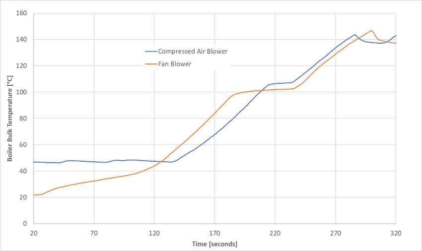
In the chart you can see the initial rate of climb in temperature before the blower is switched on. In the mid-section, around 180 to 230 seconds, I turned both blowers off momentarily before then switching them back on. Note that the electric fan was removed from the chimney when it was turned off. Both blowers were switched off when the temperature got above 140°C as this is then close to the 50psi safety valve limit.
 
Model ducted fans are inexpensive these days. Below is a set up for a monotube.

Lohring Miller
 

Attachments

  • P1010294.JPG
    P1010294.JPG
    374 KB · Views: 146
  • P1010296.JPG
    P1010296.JPG
    336 KB · Views: 152
  • P1010301.JPG
    P1010301.JPG
    339.9 KB · Views: 150
The major issue I can see with using a ducted fan is that you're exposing both the plastic fan and the motor to the hot gas stream. Not something I'd want to do long term. Most manufacturers don't like to see their equipment running at temperatures above 104°C, they will sometimes go up to 140°C but not often. I don't know what the exhaust temperature would be, but I suspect that it would be higher than that.

If, because they're inexpensive, you consider this to be something that you use until it dies and then throw it away and get antoher - that's another story.

Don
 
The fan is at the intake to the burner. Its housing is aluminum with only the fan in plastic. The incoming air flow at normal temperatures should cool the plastic parts well below the problem area. Temperatures will only rise downstream from the burner.

Lohring Miller
 
The fan is at the intake to the burner. Its housing is aluminum with only the fan in plastic. The incoming air flow at normal temperatures should cool the plastic parts well below the problem area. Temperatures will only rise downstream from the burner.

Lohring Miller
Hi Lohring, ok, this sounds like you are blowing air into the furnace rather than sucking air out of the chimney.
 
Lohring:

Nigel's blowers sat in the exhaust stream. I thought you were doing the same thing, that's why I made the comment about the temperature.

Don
 
there have been some larger scales using a blower fan on the exhaust venturi style so as not to expose the fan to hot gas, some have used a compressed air fitting coupled to the blower ring in the stack. There is a limit as to how fast you want to raise temp. on these things.
 
there have been some larger scales using a blower fan on the exhaust venturi style so as not to expose the fan to hot gas, some have used a compressed air fitting coupled to the blower ring in the stack. There is a limit as to how fast you want to raise temp. on these things.
There is definitely a limit to how fast you want to raise the temperature. The maximum 350W of heat input to the boiler is a tad scary on this very small boiler as things start to happen very fast.
 
Hi
Has anyone considered using the Coanda effect as demonstrated in this YT Video?

The conceptual layout I have in mind is shown in the drawing below.
This is a cross section of shaped tube (blue) that slides into the top of the stack (yellow). Down the centre of the tube is a bladeless fan core (pink).
Air would be sucked up the stack by air flowing through the core due to the Coanda effect.
Flow through the core (blue) would induct air through the centre and entrain air around the sides. A small flow of low pressure air through the core should result in a larger flow through the stack.

Air supply for the core could come through hollow struts (not shown) supporting the core. The air supply (now shown) could be a standard low pressure, low cost plastic electric fan. Something like a 12V centrifugal blower from a computer would be ideal.

The advantages with this system would be:
  • no moving parts in the hot air stream,
  • a low pressure air supply is usually low noise and low cost.
  • the air supply (eg electric fan) is separated from high temperatures.
  • air flow is amplified.
I am far away in time from needing a blower but I would start by 3D printing plastic prototypes to test and develop with cold air.
I would make the final version from spun sheet metal for the round parts.

This would also make a good project for an Engineering student to model with CFD.
This concept could possibly be applied to improve blast pipe design. An electric fan could be replaced by steam exhaust within the stack.


Dazz
 

Attachments

  • Blower.jpg
    Blower.jpg
    58 KB · Views: 153
Last edited:
I assuming you're running your fan at the same power levels as when you ran it out of the boiler (~5.6 volt / ~.46 amps.) This would equal 2.6 watts of power consumed by the electric fan.

Now, assuming 10% loss in your power supply, 10% Loss in power transmission from the grid, and 60% loss at the power generation plant: The power consumed to run the electric motor is about 11 watts.

Therefore, you're increase of burn rate is more like 270 watts and not 300 watts.

Note that 300 watts is about 2/5 horsepower.

I have a 1/4" HP steam engine and it requires a boiler much, much larger than the one you have in your video. Given a thermal efficiency of about 5%, that means my 1/4 HP steam engine consumes about 3.7 kw of heat energy.

If you're putting in 300 watts of power to a model steam engine running at 5% thermal efficiency, the same calculation would result in a steam engine putting out about 15 watts when using your blower. Without your blower, the power output at the steam engine shaft would be about 3 watts.

Does anyone have a small model engine running a light bulb where the volt-amps can be calculated? It would be interesting to calculate the true power output and thermal efficiency of these small model steam power plants.

I wonder if you really went old school and ran the blow pipe off the generated steam itself, would you get the same increase in power?

BTW: I like your blower design. The impeller looks impressive. It's unfortunate that it's required to be totally enclosed for the machine to work.

...Ved.
 
The output from the steam engine is very low and I would assume overall the efficiency is somewhere around 0.5% to 2% if it was all optimised.

As yet I haven't calculated the heat output of the meths burner or the mass of methylated spirits that is burnt. I will see if I can place the whole system on a set of scales and measure the use of meths with and without the blower operating.

Then using the lower heating value for meths I can calculate an overall efficiency, the lamp post engine drives a generator and I could measure the power output from this.

Using steam to improve the draft is fairly normal, but during startup this is not available.
 
Back
Top