Steam pipe and base

Home Model Engine Machinist Forum

Help Support Home Model Engine Machinist Forum:

This site may earn a commission from merchant affiliate links, including eBay, Amazon, and others.

deere_x475guy

Well-Known Member
Joined
Oct 26, 2007
Messages
900
Reaction score
13
Location
Eaton Rapids MI
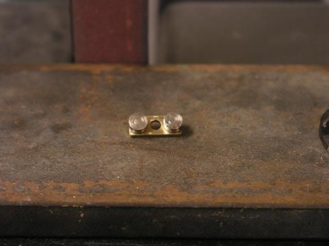
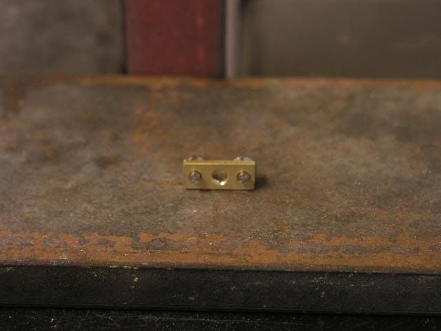
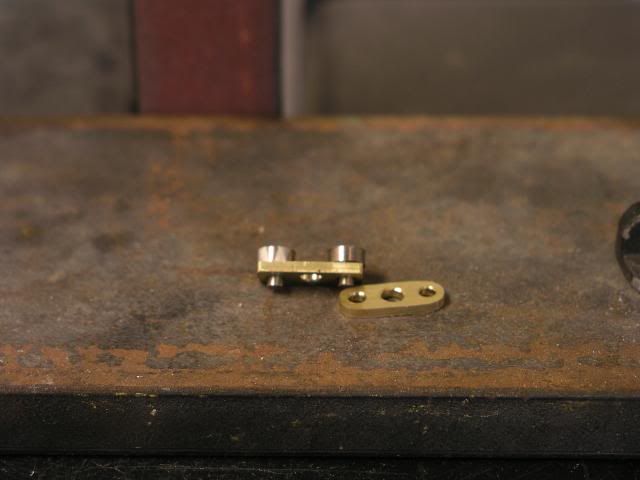
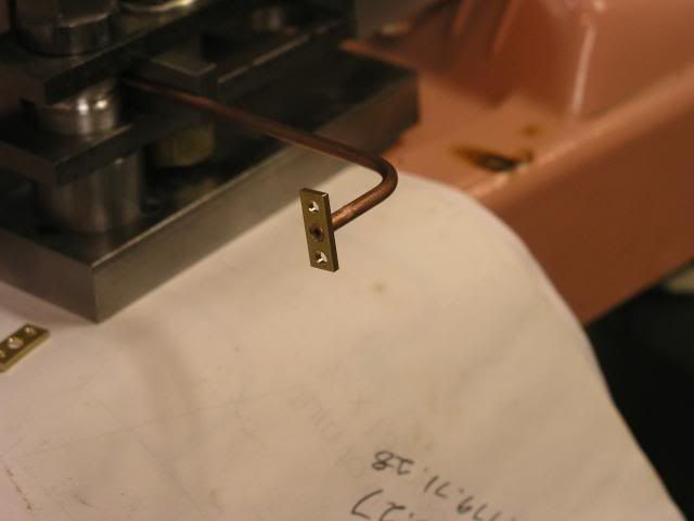
Well I have the bases all machined and last night I finished up making the bending die, follow block and clamping blocks so I could start bending the piping.

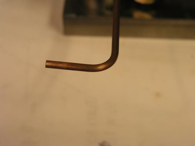
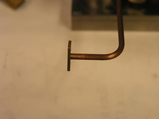
Here is how the first one came out. I have 1.099 from the end of the pipe to the centerline. The plans call for .9375 so there is some wiggle room here.

I am going to cut the second leg of the pipe to approx .950. Best I can tell from the plans this end of the pipe should end at the end of the bearing. The dimensions I come up with are .9375 so .950 will give a little wiggle room here.
P1010500.jpg


P1010502.jpg


P1010503.jpg


I should have these finished up this morning and then I will start on the Steam connector. I am using hex and plan to follow what Tim (tin falcon) has done in the past.
 
Bob, don't know if it helps but here is the drawing from the models I made.
Tim

piping.jpg
 
Looking great Bob!!! I can see I'm going to have to build one of those benders. They do an excellent job.

Wes
 
Thanks Powder, I need to talk to Tim (zeusrekning) because it looks like I came up short. Just got to find his number. Tim if you on call me if you still have my number.
 
Tim thanks for getting my thinking straight this morning. I have all the pipes cut now. They are all slightly longer for trim at final assembly.
 
Are you going to shape the ends of the plate that goes on the end f the pipe? Have you decided how you are going to do it? You could set that up in the mill pretty easy. I'd mill the angle then just file the radius?

Wes
 
Right now I am trying to figure how I am going to get the raduis on the ends of the pipe plate so that they all look the same.
maybe put some rod though a couple of holes for alignment put in a vice, file and smooth with silicon carbide paper if they are all stacked together they will be the same or real close.
Tin
 
Ok I have them all shaped and 6 out of the 12 have been polished so there are no machining marks left. This is what I ended up doing.

In the pic below you will see two pins pushed through the 3/32nd holes. The larger diameter on these pins is .218, which will give me the radius called for in the plans. The larger heads on these pins acted as a sanding stop so that I could get a reasonably close matching radius on both ends.

P1010505.jpg


P1010506.jpg


P1010507.jpg


With a bit more time I will have the other 6 polished up.


Bob
 
Bob, that turned out really good.The sanding stops were a good idea.
Tim
 
Thanks guys, I used this technique before and posted to the site (can't remember right now which post it was and a search didn't get me anything). Anyway I didn't jump right on this idea at first because of two reasons:

1. Parts are tiny and I was a little intimited of having my fingers that close to the sander.

2. There is a large gap between the belt and the table. Larger than the 2.18 dia of the guide pin.

Any way I clamped a piece of flat bar stock up close to the belt to cure the gap problem. And by having a guide pin at each end I was able to pivot the part pretty easily keeping my fingers away from the sanding belt. My hands finally loosened up a bit and the pain lessend around 11:00 so I went at it. I am pretty happy with the way things turned out.


Latest posts

Back
Top