Spoked wheels

Home Model Engine Machinist Forum

Help Support Home Model Engine Machinist Forum:

This site may earn a commission from merchant affiliate links, including eBay, Amazon, and others.

Oldmechthings

Well-Known Member
Joined
Jan 10, 2008
Messages
153
Reaction score
12
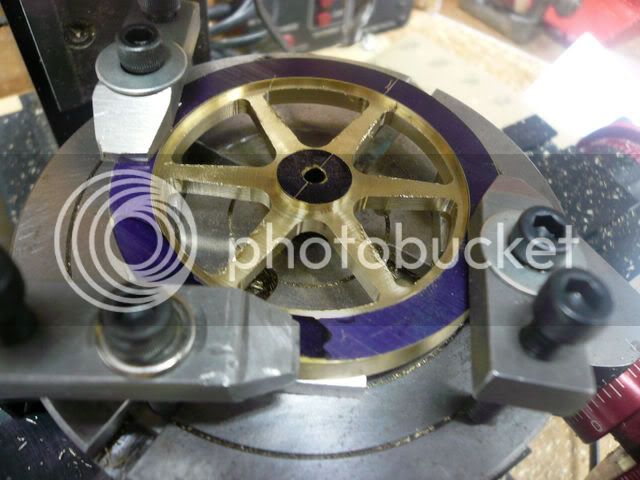
Today I'm in the process of machining some spokes cable sheaves for the steam shovel. The operations are similar whether your making a sheave, a gear, or a flywheel. I thought that those new to the hobby might be interested in the process. These are fairly small being 2 1/2" diameter and 3/8" thick. First rough blanks were sawed from some plate steel, then blued and laid out. Under size pilot holes were drilled at what would end up being corners. A hole was drilled and reamed in the center. It will eventually be fitted with a brass bushing. Then the blank was put on a mandrel where the O.D. and sides were turned in the lathe. On this particular job I drilled a 3/8" hole in the center of each space after turning, just to hog out some metal. I don't always do that. Then the part is moved to a three jaw chuck on a homemade rotary table on the milling machine. The circular arcs are milled by simply turning the table and leap frogging over the spokes. The sides of the spokes are milled by traversing the mill table, and indexing the table the proper number of degrees for each spoke. Spokes are nearly always tapered from the hub out to the rim. These sheaves have a 6 degree included taper. That needs to be taken into consideration when setting up, but is easy enough to do with the rotary table.

P1280002.jpg


P1280003.jpg


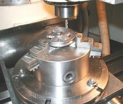
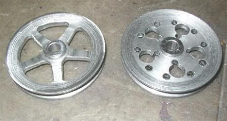
The first picture shows a sheave in the process of milling the spokes, and the second picture shows two sheaves. One after turning, but before milling, and the other one after the spokes have been milled. The spokes come out rectangular in shape, and the could be rounded of with a radius cutting mill, but it is hard to find a cutter the right size to fit those tiny spaces. So I just use a file, and within a couple minutes can have the corners rounded enough to look ok. The rounding is cosmetic anyway, so it does not matter if it is not perfect.
Try it you might like it.
Birk
 
Oldmechthings said:
... The sides of the spokes are milled by traversing the mill table, and indexing the table the proper number of degrees for each spoke. Spokes are nearly always tapered from the hub out to the rim. These sheaves have a 6 degree included taper. That needs to be taken into consideration when setting up, but is easy enough to do with the rotary table.

Hello Birk,
I realize this is an older post but I'm hoping you could respond to this. I follow the entire process for machining the spoked flywheel but if you could please elaborate a little on setting up the RT to cut the taper I would be very grateful.
The plans for the engine I'm working on call for spokes on the flywheel and I really want to tackle that part of the job and not duck it with a alternative design.

Thanks

Jim
 
JMI--I could have this wrong, but--I believe you only use the rotary table to cut the arcs in the blanks. The actual cuts for the sides of the spokes are made by traversing the bed of the milling machine.---Not a big deal if you keep the sides of the spokes parallel.-However, if you want tapered spokes, then you have to incorporate the angle of the taper into the way your part sets in relationship to the travel of the mill table. If I have this wrong, somebody please jump on board here and correct me.---Brian--(Perhaps I misunderstood the question. In order to index the rotary table the correct number of degrees to get the taper on the spokes will call for some mathematical calculations or good full scale layout work.--sorry if I confused anyone---sometimes my answers confuse me.)
 
Now I am confused because I read Birk's description and Brian's description saying the same thing.

I am impressed with Birk's 3 jaw that it is accurate enough for that kind of work. I have both a small 3 jaw and a small 4 jaw that I move from the lathe to the mill without disturbing the workpiece.
 
Marv's flywheel program will calculate the DRO positions for the pilot holes for any size wheel and # of spokes.

If I build Brian's double size engine I think I will use a spoked wheel to try it out.
 
I've made enough tapered spoke flywheels that I wrote a program to work out all the numbers and print a chart that can be carried to the shop and used as a guide during the machining.
The program is called FLYWHEEL and can be freely downloaded from my webpage (URL in my sig).

After the "corner" holes marking the space between spokes are drilled, it's necessary to rotate the rotary table by a slight angle in order to bring the edge of the (tapered) spoke parallel with one of the milling machine axes. Then the mill table is translated slightly to align the edge of the cutter with the edge of the spoke so that cutting may begin. After doing this for one spoke, it's a simple matter of just indexing the table angle to align the other spokes for cutting. A similar process aligns the other side of the spoke for cutting.

The attached diagram (part of the downloadable FLYWHEEL archive) shows the layout and the associated mathematics that are implemented in the program.


FLYWHEEL.jpg
 
Having just used Marv's program to mill this spoked flywheel, I can tell you the program is well worth downloading. It works great!

P1020629.jpg


A word of caution. Make sure you read the introductory notes regarding the download and Windows idiosyncracies. I found out the hard way that ***NOTA BENE*** wasn't an abbreviation for "Not a Benefit".

Regards,
Dennis
 
mklotz said:
After the "corner" holes marking the space between spokes are drilled, it's necessary to rotate the rotary table by a slight angle in order to bring the edge of the (tapered) spoke parallel with one of the milling machine axes. Then the mill table is translated slightly to align the edge of the cutter with the edge of the spoke so that cutting may begin. After doing this for one spoke, it's a simple matter of just indexing the table angle to align the other spokes for cutting. A similar process aligns the other side of the spoke for cutting.

Nice piece of work Marv. Please bear with me for some clarification.
As per your drawing and the flywheel.out demo file generated by your program:
After locating/drilling all the holes the RT would be turned clockwise the value of "phi" and then the table is moved right to left to the cut line (the value of x plus half the diameter of cutting tool). I follow this.
Here is where I need clarification. In order to index the same side of the next spoke the rotary table would be advanced counter-clockwise the value in degrees for the next spoke as determined by your program, in the case of the demo, the outer hole value of 67*? This will line the edge of the cutting tool with the cut line?

Thanks much for the help.

Jim
 
Jim,

Once you're aligned to mill the edge of one spoke, all you need to do is rotate 360/N (N = number of spokes) to align for the next spoke. In the case of the demo, N is six, so 360/N is 60 degrees.

Think about it this way...

Once you've aligned to mill the edge of one spoke, the centerline of that spoke is at some location in space. After you rotate the table by 360/N, the centerline of the next spoke will lie in that same location in space. Therefore, the edge of that spoke must now lie in the proper location to be milled, i.e., the same location as the edge of the spoke just machined.

If you're confused about the process, I recommend that you try it first with a bit of scrap (even wood or masonite will do) before committing to a real part.

Dennis wrote:

A word of caution. Make sure you read the introductory notes regarding the download and Windows idiosyncracies. I found out the hard way that ***NOTA BENE*** wasn't an abbreviation for "Not a Benefit".

Thanks for warning them. [For those who don't know what we're on about here, I have a low boiling point when asked questions about things I've already answered in the documentation that accompanies the programs.]

Nota bene (usually abbreviated as NB) is Latin for "note well" and is used to alert the reader to information that is essential to his understanding of what is being written about.

I might also point out that most of the programs written by me are accompanied by an ASCII text file (*.txt) describing the program and its use. Make a point of reading same before using the program.


Marv,

I would just like to point out to people, when they see me banging out spoked wheels as if there is no tomorrow.

Most of them start out as generated coordinates from Marv's great program, and it is well worth getting to know how to use it. It halves the time it takes to make good spoked flywheels. It is just like doing a dot to dot puzzle.

John
 
Marv,
Many thanks for providing an easy solution for a problem that would have had me scratching/banging my head forever.

Jim
 

Latest posts

Back
Top