


Hi all;
Some of you may have seen my little mashed up gear that let loose in the post about making a spindle
adapter for the little Atlas. It quit the job in the middle of that project, and the time has come to make
its replacement.
This post will deal with the method I use to cut gears in my shop. I'm not a real life machinist. Just an
impersonator. The way things are shown here are the way they work for me, and have done for quite
a few years. That doesn't mean they are the pro way of doing things, or maybe not even a preferred
method.
Cutting gears involves using single point gear cutters, in my shop, at least. Factory made involute gear
cutters just cost too much, for me. There have been scores of gears cut in my shop using this type of
cutter, and it works well on most free cutting metals. I don't think it will hold up against metals like
1018, or HRS. They are just a bit too tough on cutters that depend on an interrupted cut.
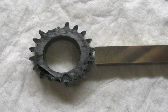
Here's that broken gear, and the 1/4" HSS tool bit that will be ground to cut the teeth of a new gear.
To grind it, just head on over to the bench grinder and start getting rid of what ever won't fit into the
space between two teeth on the old gear. It can take a while, and may take a few tries to get it to fit.
I use an Opti Visor so I can see close up when doing this.
When you have the shape pretty close, the last tiny bit that needs to be taken off involves barely
touching the tool bit to the grinding wheel. Check it after each little spark comes off the tool bit. It will
suddenly go from an obvious wrong shape, to a fairly good fit.
When I get it so close that I'm afraid to take another touch on the bench grinder for fear of ruining it, I
use a Dremel tool with a small diamond bit to finish it off. The Dremel tool is clamped to the work
bench, and the tool gently massaged to shape. Trying to do it with the tool bit in one hand, and the
Dremel in the other hand is like trying to hit a sewing needle with a sledge hammer. Putting the Dremel
in a stationary mount or vise makes things much easier.
After a bit of grinding, I have the tool bit to a pretty close match to the old gear teeth. I won't make
any claim about getting it perfect. Only as perfect as I can get it by eye. It needs to cut a close
approximation of the curve on the original gear.
If the gear you have is badly worn, i.e. teeth are thin, or leaning to one side, you will have to find one in
better shape to use as a model for grinding your tool. You also have to use a gear that is close to the
same tooth count. There is a reason for that. The shape of gear teeth change as the gear tooth count
goes up. The teeth on a gear with a tooth count of 20 look a little different than those of a gear with
64 teeth. So, match up your cutter to a similar gear as you want to cut.
I had cutters already ground for this gear pitch, but they were for different tooth counts, and didn't
quite fit the profile of the teeth in the gear that needs to be made here.
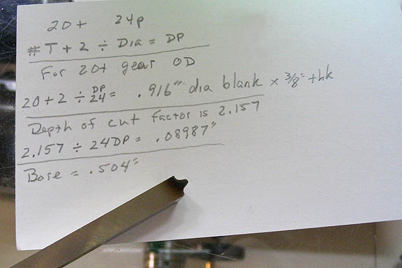
Okay, with the cutter done, I write down all the needed info to make a new gear blank. The main
things I need to know are the diameter of the blank, along with it's thickness and bore, and the depth
to cut the teeth.
I have a couple of books that tell all kinds of stuff about gears. Most of it is not really useful, or maybe
I just don't get it. The things really needed are on the sheet of paper in the picture, above.
Figuring the diameter or the pitch of a gear can be done provided you know at least one of those two
things. You can also figure pitch of one gear by using another gear of any size that it will mesh with.
For instance, if you have a gear that's been broken into pieces, and say you only have 1/3 of the gear
left. You can't measure the OD of that! Find a whole gear that it will mesh with, and determine the
pitch of the whole gear.
I think my scratchings in the picture tell what I did. One thing that may not be clear is for the depth of
cut for the teeth. That one number, 2.157, is a constant, and can be used for all regular pitches. This
works with American style involute pitches. I can't remember if it is the same for metric gears, and I've
never cut metric, outside of clock wheels.
With that stuff done, it's time to cut a blank for the gear.
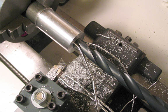
The bore for this gear is .504", and I figured a drill bit would get it close. It came out right at that
number using a 1/2" bit. The piece is faced off to make a square surface and then parted off. Put that
piece in the chuck with a piece of tool steel backing it up to keep it square while the jaws are tightened,
the tool steel piece is removed, and the other side faced to a length of .375".
That's it for the blank for the moment.
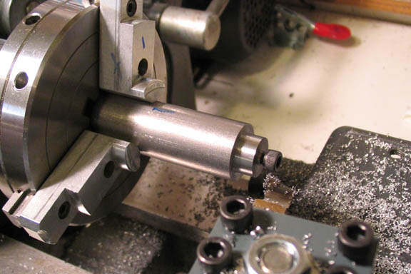
Now an arbor is made up to hold the blank. Once this arbor is made, it is not removed from the chuck
until the gear is done.
A stub is turned on the end to match the bore of the gear blank, and a little short of the thickness of
the blank, so the cap screw in the end of the arbor can squeeze down on the blank and hold it fast.
Right behind the stub for the gear blank, a short distance is turned down to a diameter that is under the
depth of cut for the teeth. This will keep the cutting tool from dragging steel chips through the
aluminum gear blank when it is cut. If the gear were a larger OD, this wouldn't be necessary, as the
cutter wouldn't be going close to the arbor to take the cut.
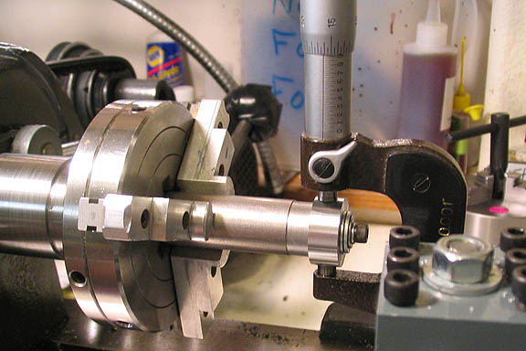
Now, the blank is put on the stub, tightened down nice and tight, and turned to the diameter needed for
the gear. From this point on, the blank is not disturbed or removed from the arbor, and again, the
arbor is not removed from the chuck. Every thing should be happy in this relationship.
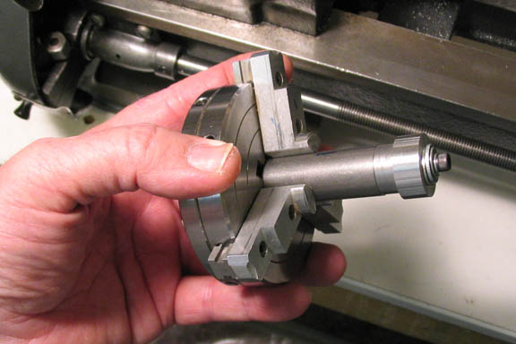
With the arbor and gear blank all made up in the same chuck setup, the chuck can be removed...
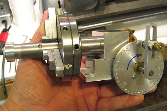
...and mounted on the dividing head.
The gear I want to cut here will have 20 teeth. Time to figure out how much cranking I want to do on
the handle between cuts. These numbers are particular to my dividing head, and any like it that use the
same worm gear tooth count, (which is probably not very many). Never the less, this is the way it is
done for any simple dividing head. Just plug in the number of the worm in your dividing head, and you
should be good.
This dividing head has a 100 tooth worm gear. I have a few division plates for it, and choose a plate
with 40 holes. Multiply the number of division holes by the tooth count of the worm gear, and you
have the total number of divisions possible with that setup. 40 x 100 = 4000. So there are 4000
possible divisions.
I want 20 teeth; 4000/20 = 200. That means I need to advance the crank on the dividing head 200
holes for each tooth to be cut on the gear. Instead of counting all those holes each time, the number
of holes in one rotation of the crank on the division plate can be divided into the total number of holes
needed to get full rotation turns of the crank, plus any remaining holes needed. In this case, 200, (the
number of holes to advance for each cut) divided by 40, (the number of holes in the division plate) tells
me the full turns; 200/40 = 5. Well, that's lucky. Exactly five turns of the crank for each cut on the gear.
It doesn't always work out that way, but I'll take it when I can get it.
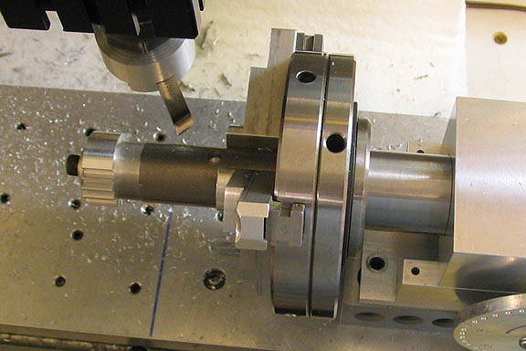
After setting the dividing head square to the mill table, its crank handle is set to the "0" mark.
The cutter is set on center line of the gear blank. With the tip of the cutter against the OD of the blank,
the Y axis dial is set to zero. Move the cutter out of the way a bit, and crank the X axis back enough
so the cutter won't bash the gear blank on start up. Give the cutter a turn by hand to make sure it
doesn't hit the chuck jaws when the X axis is at its starting point. Dial in a few thou on the Y, run the X
to the right to make a cut, and return to zero. Keep dialing in Y a few thou and running the X back and
forth until the depth of cut is reached.
Stop the mill, crank in my five turn on the dividing head and return the Y dial to zero.
Repeat until there are no more places to put teeth on the blank.
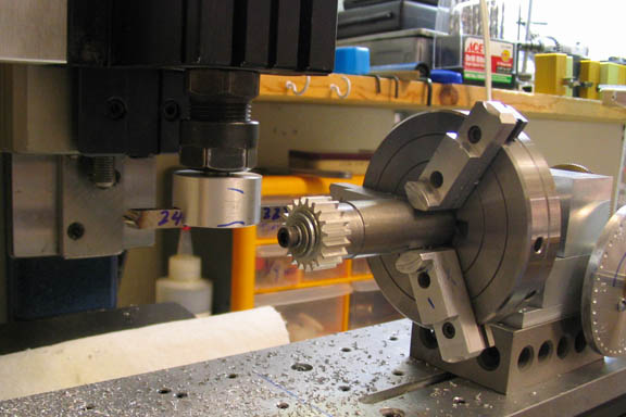
Here's the last cut, just done.
Look it over well to see if they all appear to be the same, (hopefully!).
There's usually no going back once you take the gear off the arbor.
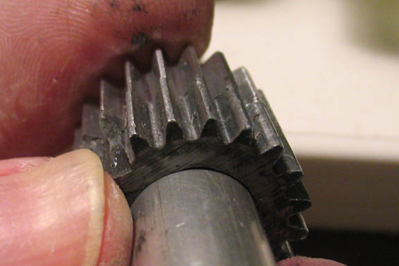
I checked the new gear against the old busted bit. Pretty close, though I have bumped them slightly
out of time trying to hold still for the picture.
I put the new one in it's place and turned the lathe spindle 'round and 'round, and 'round a bunch more,
waiting for a tight spot that never showed up. Okay, then.
This short vid shows the new gear in its place, doing its thing. It's the gear directly below the spindle
gear. All of the running gear is engaged in the vid, including the back gear, so you can hear a lot of gear
noise. That's the way it sounds, though the camera seems to amplify everything.
[ame]http://www.youtube.com/watch?v=Vmmuh9ZylZ4[/ame]
Thanks for having a look.
Dean
Some of you may have seen my little mashed up gear that let loose in the post about making a spindle
adapter for the little Atlas. It quit the job in the middle of that project, and the time has come to make
its replacement.
This post will deal with the method I use to cut gears in my shop. I'm not a real life machinist. Just an
impersonator. The way things are shown here are the way they work for me, and have done for quite
a few years. That doesn't mean they are the pro way of doing things, or maybe not even a preferred
method.
Cutting gears involves using single point gear cutters, in my shop, at least. Factory made involute gear
cutters just cost too much, for me. There have been scores of gears cut in my shop using this type of
cutter, and it works well on most free cutting metals. I don't think it will hold up against metals like
1018, or HRS. They are just a bit too tough on cutters that depend on an interrupted cut.
Here's that broken gear, and the 1/4" HSS tool bit that will be ground to cut the teeth of a new gear.
To grind it, just head on over to the bench grinder and start getting rid of what ever won't fit into the
space between two teeth on the old gear. It can take a while, and may take a few tries to get it to fit.
I use an Opti Visor so I can see close up when doing this.
When you have the shape pretty close, the last tiny bit that needs to be taken off involves barely
touching the tool bit to the grinding wheel. Check it after each little spark comes off the tool bit. It will
suddenly go from an obvious wrong shape, to a fairly good fit.
When I get it so close that I'm afraid to take another touch on the bench grinder for fear of ruining it, I
use a Dremel tool with a small diamond bit to finish it off. The Dremel tool is clamped to the work
bench, and the tool gently massaged to shape. Trying to do it with the tool bit in one hand, and the
Dremel in the other hand is like trying to hit a sewing needle with a sledge hammer. Putting the Dremel
in a stationary mount or vise makes things much easier.
After a bit of grinding, I have the tool bit to a pretty close match to the old gear teeth. I won't make
any claim about getting it perfect. Only as perfect as I can get it by eye. It needs to cut a close
approximation of the curve on the original gear.
If the gear you have is badly worn, i.e. teeth are thin, or leaning to one side, you will have to find one in
better shape to use as a model for grinding your tool. You also have to use a gear that is close to the
same tooth count. There is a reason for that. The shape of gear teeth change as the gear tooth count
goes up. The teeth on a gear with a tooth count of 20 look a little different than those of a gear with
64 teeth. So, match up your cutter to a similar gear as you want to cut.
I had cutters already ground for this gear pitch, but they were for different tooth counts, and didn't
quite fit the profile of the teeth in the gear that needs to be made here.
Okay, with the cutter done, I write down all the needed info to make a new gear blank. The main
things I need to know are the diameter of the blank, along with it's thickness and bore, and the depth
to cut the teeth.
I have a couple of books that tell all kinds of stuff about gears. Most of it is not really useful, or maybe
I just don't get it. The things really needed are on the sheet of paper in the picture, above.
Figuring the diameter or the pitch of a gear can be done provided you know at least one of those two
things. You can also figure pitch of one gear by using another gear of any size that it will mesh with.
For instance, if you have a gear that's been broken into pieces, and say you only have 1/3 of the gear
left. You can't measure the OD of that! Find a whole gear that it will mesh with, and determine the
pitch of the whole gear.
I think my scratchings in the picture tell what I did. One thing that may not be clear is for the depth of
cut for the teeth. That one number, 2.157, is a constant, and can be used for all regular pitches. This
works with American style involute pitches. I can't remember if it is the same for metric gears, and I've
never cut metric, outside of clock wheels.
With that stuff done, it's time to cut a blank for the gear.
The bore for this gear is .504", and I figured a drill bit would get it close. It came out right at that
number using a 1/2" bit. The piece is faced off to make a square surface and then parted off. Put that
piece in the chuck with a piece of tool steel backing it up to keep it square while the jaws are tightened,
the tool steel piece is removed, and the other side faced to a length of .375".
That's it for the blank for the moment.
Now an arbor is made up to hold the blank. Once this arbor is made, it is not removed from the chuck
until the gear is done.
A stub is turned on the end to match the bore of the gear blank, and a little short of the thickness of
the blank, so the cap screw in the end of the arbor can squeeze down on the blank and hold it fast.
Right behind the stub for the gear blank, a short distance is turned down to a diameter that is under the
depth of cut for the teeth. This will keep the cutting tool from dragging steel chips through the
aluminum gear blank when it is cut. If the gear were a larger OD, this wouldn't be necessary, as the
cutter wouldn't be going close to the arbor to take the cut.
Now, the blank is put on the stub, tightened down nice and tight, and turned to the diameter needed for
the gear. From this point on, the blank is not disturbed or removed from the arbor, and again, the
arbor is not removed from the chuck. Every thing should be happy in this relationship.
With the arbor and gear blank all made up in the same chuck setup, the chuck can be removed...
...and mounted on the dividing head.
The gear I want to cut here will have 20 teeth. Time to figure out how much cranking I want to do on
the handle between cuts. These numbers are particular to my dividing head, and any like it that use the
same worm gear tooth count, (which is probably not very many). Never the less, this is the way it is
done for any simple dividing head. Just plug in the number of the worm in your dividing head, and you
should be good.
This dividing head has a 100 tooth worm gear. I have a few division plates for it, and choose a plate
with 40 holes. Multiply the number of division holes by the tooth count of the worm gear, and you
have the total number of divisions possible with that setup. 40 x 100 = 4000. So there are 4000
possible divisions.
I want 20 teeth; 4000/20 = 200. That means I need to advance the crank on the dividing head 200
holes for each tooth to be cut on the gear. Instead of counting all those holes each time, the number
of holes in one rotation of the crank on the division plate can be divided into the total number of holes
needed to get full rotation turns of the crank, plus any remaining holes needed. In this case, 200, (the
number of holes to advance for each cut) divided by 40, (the number of holes in the division plate) tells
me the full turns; 200/40 = 5. Well, that's lucky. Exactly five turns of the crank for each cut on the gear.
It doesn't always work out that way, but I'll take it when I can get it.
After setting the dividing head square to the mill table, its crank handle is set to the "0" mark.
The cutter is set on center line of the gear blank. With the tip of the cutter against the OD of the blank,
the Y axis dial is set to zero. Move the cutter out of the way a bit, and crank the X axis back enough
so the cutter won't bash the gear blank on start up. Give the cutter a turn by hand to make sure it
doesn't hit the chuck jaws when the X axis is at its starting point. Dial in a few thou on the Y, run the X
to the right to make a cut, and return to zero. Keep dialing in Y a few thou and running the X back and
forth until the depth of cut is reached.
Stop the mill, crank in my five turn on the dividing head and return the Y dial to zero.
Repeat until there are no more places to put teeth on the blank.
Here's the last cut, just done.
Look it over well to see if they all appear to be the same, (hopefully!).
There's usually no going back once you take the gear off the arbor.
I checked the new gear against the old busted bit. Pretty close, though I have bumped them slightly
out of time trying to hold still for the picture.
I put the new one in it's place and turned the lathe spindle 'round and 'round, and 'round a bunch more,
waiting for a tight spot that never showed up. Okay, then.
This short vid shows the new gear in its place, doing its thing. It's the gear directly below the spindle
gear. All of the running gear is engaged in the vid, including the back gear, so you can hear a lot of gear
noise. That's the way it sounds, though the camera seems to amplify everything.
[ame]http://www.youtube.com/watch?v=Vmmuh9ZylZ4[/ame]
Thanks for having a look.
Dean