Solidworks, models & fasteners

Home Model Engine Machinist Forum

Help Support Home Model Engine Machinist Forum:

This site may earn a commission from merchant affiliate links, including eBay, Amazon, and others.

petertha

Well-Known Member
HMEM Supporting Member
Joined
Jun 24, 2010
Messages
2,357
Reaction score
931
I’m slowly beavering my way through Solidworks books & tutorials towards doing some model engine type 3D modeling, hopefully soon. One aspect that is still not clear to me is the issue of integrating typical fasteners into assemblies & how they are best represented. What I mean is, SW has an awesome selection of ‘hole’ tools from drop-downs menu's. You can specify bolt types, threads, countersinks, counter bores, metric/imperial etc. & it will sink the appropriate tap drill or clearance size holes no problem. So far so good, that’s what I want represented on the drawings.

But now what about the fastener itself? For example, If I now want to bring in a representative 4-40 socket cap screw into the assembly & mate it to this tap hole, are there (free) catalogs of fasteners available? I’ve found some public domain type fasteners, usually from vendor lists. But sometimes they don’t offer smallish sizes to what model engineers would use or graduated stock/purchase lengths. Also (I might be wrong here) it appears they have the full helical thread detail on them? If so, I’m thinking this is overkill & just making assembly files unnecessarily large & complex. I’m not intending to do strength calculations. My hunch is a suite of ‘blank’ bolt shanks with cosmetic threads would be good. Are these available? If so, are they sized to typical thread OD’s & then assembled as a coincident (interference) fit into the target tapped hole?

Hopefully from some folks who do this for a living can steer me down the right track. I’m pretty sure I could draw some generic fasteners from specs to build a personal parts library, but seems like extra work. Using SW-2011 btw.
 
Hello Petertha
If you want to use fasteners in your drawings, first create these with the toolbox. If you have done that, save these items in the same file as you drawing. Then, with insert components, you can use your fasteners.
Nemt
 
Peter-

I have found a few fasteners online, but they do have a lot of detail in them, and I am not sure I could mate them correctly.

The full thread does seem like overkill, and is not necessary in my opinion (affects file size too like you say).

I have not addressed tolerances yet, and have been drawing everything to exact size in order to get the correct mate.
I draw a hole for a 1/4" screw at 0.25", and draw the fastener also at 0.25", but at some point I will need to address tap drill sizes on the drawings, maybe with just a manual call out.

Anyone else run across this.
How are tolerences/ drill tap sizes, mates handled?

Pat J
 
Solidworks has its own incredible array of fasteners, but you only have them if you buy Solidworks Office, or one of the more expensive versions. If you only have Solidworks Basic, you do not have access to the fasteners nor the "toolbox".--then it becomes a matter of creating your own database of standard fasteners in a seperate file and using them as required. Since adding anything other than "cosmetic threads" adds a great deal to the file size, consequently making large assemblys difficult to manipulate, it is better to not go into detail with the threads----Brian
 
Brian Rupnow said:
Solidworks has its own incredible array of fasteners, but you only have them if you buy Solidworks Office... If you only have Solidworks Basic, you do not have access to the fasteners nor the "toolbox.

Yes, I have basic SW & that's exactly how I interpreted the situation. So, would you happen to know if typical bolt fasteners available through the more extensive SW-Office version would be cosmetic threads applied on straight bolt shank type method?

The tapped hole from the SW menu selection is always going to be smaller of than the nominal bolt OD. And thats what I'll be require for real life machining. But when it comes to mating the bolt in cad 3d assembly so its fully defined, is it sufficient/acceptable to make the 2 (bolt & hole) diamters concentric + define the bolt head 'seating'/depth? (resulting in what I'm loosely calling interference).

I'm kind of surpised there isn't an extensive supply of public domain fasteners available.
But maybe I havent googled in the right places yet or there is some other underlying reason.

 
To fully define a "home made" model of a bolt, use a concentric mate on the body, a coincident mate between the underside of the head and the surface which it sets against, and a parallel mate between one of the hexagonal sides and anything parallel to it. On a shcs use a parallel mate on the inside hexagonal surface of the allan key hole and any other "parallel " surface. Note that when you first try to put on a parallel mate it will default to a coincident mate and you will get an error message untill you manually select "parallel" from the drop down list in the mates dialogue box. Remember--If you create your own fastener data-base, you only have to model the head once and the shank once. Then on future lenghts of the same fastener, just use the "save as copy" function, save the fastener as the length you want, then go in and edit the length of the shank---the head will always remain a constant.
 
I have noticed that there are only a few sizes of bolts/fasteners that I use on models, and generally they are a #6,8,12, 1/4", 5/16", and occasionally a 3/8".

I use either a hex head or filister head only, with an occasional hidden cap head screw if I just can't make anything else work.

It would not take very long to draw these sizes and types, especially without threads.

It would be nice if the forums would stock 3D files of these typical fasteners in their download section.

It may also be possible to download some of the pre-drawn fasteners, such as from McMaster-Carr, and just delete the thread.

Who is going to start a 3D parts standard for HMEM?

Pat J
 
Mcmaster carr has models of just about everything they sell.

Here is a link to a 1-72 SHCS.

http://www.mcmaster.com/#cadinlnord/91251a064/=dnaeup

When you click on save, then go to the saved folder, you can drag it right into SW.

It comes with the thread detail, but as a SW file you can easily delete the swept cut, which formed the thread, to save on file size, or processing speed.

There is another vendor which allows you to specify the level of detail in the download, but I can't remember who, just now.

Have fun!

Edit: Just saw Pat's response. Like he said.


KustomKB said:
Mcmaster carr has models of just about everything they sell....It comes with the thread detail, but as a SW file you can easily delete the swept cut, which formed the thread, to save on file size, or processing speed.

Awesome!
Now that I think about this some more, it may have been Mcmaster that I downloaded some fasteners a few years back. But I was using Rhino then and possibly picked their .iges format. Maybe thats what stuck in my head as being overly complex. But since they offer SW import directly, may as well get the bolt with threads - all the work is done. As you say, either remove the threads from the design tree for simplicity. Or for that matter, just leave it. It's just a swept cut applied to the main shank, so not really going to overload the PC unless the assembly or fastener count was huge.

OK, Im going to give this a try! I recall they also offer bearings & e-clips & other do-dads of interest to ME-types. Thanks for all the useful input.
 
A word of warning about bolts with swept cuts for threads. If you click on the threaded shank of the fastener and on the hole the fastener goes into, and try to mate them with a concentric mate, it won't work. It will attemp to give you a tangent mate instead, which is a big pain in the butt. From my perspective, and I design hundreds of machines with varying complexities, using a threaded fastener with a swept cut thread is massive overkill with no redeeming value. I don't get paid to spend the time putting "pretty" bolts onto a design. In fact, most customers stipulate that the bolts are not put into the design at all, just matching, correct sized holes. If I do put fasteners into a design, I make them pictorially correct but with a "cosmetic" thread. as long as they are billed out properly in the "custom Properties" tab in the part file, they will show up as the correct style, diameter, and length in the bill of materials.
 
In TurboCad if you use 3D subtract with keep subtrahend it's not a problem. The female thread is created from the bolt thread, (revolve/sweep).

Best Regards
Bob
 

"Fancy" parts, like threaded fasteners are easily mated by using the head for a concentric relation. As stated before the threads are mostly for cosmetic purposes.

If you want to mate other oddly shaped pieces, such as a spring, don't forget that construction planes can also be used as mates.


You (and others) need Parts? Go to tracepartsonline.net :)

Biggest Database of Parts i know of. Not just fasteners but springs, profiles. Name it - you probably will find it.
 

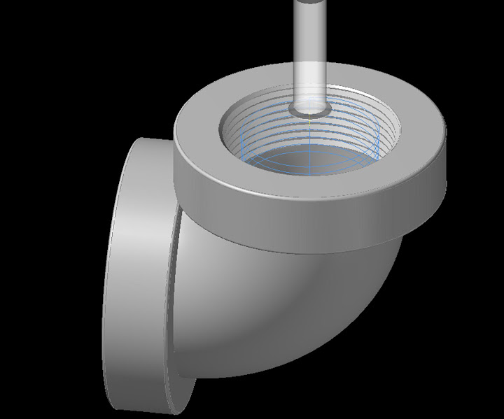
I just thought I would show an example where a machinist or client would benefit from having the threads included.

Here, a pipe thread is being single point milled with a 3-D tool path.

thread%252520mill.JPG


Back
Top