petertha said:
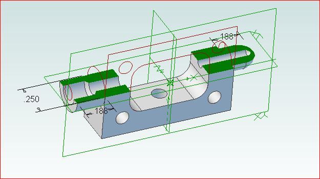
I dont want the external block part anymore, I want the resultant internal cavity part (hilighted in red) that came about by various features or operations imposed on it.
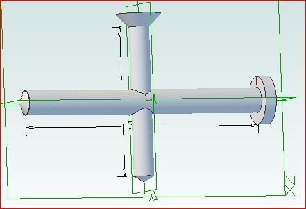
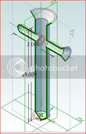
I think my example solid picture is actually confusing matters, so I'll try with again with better words. I too can replicate a simple internal cavity shape like the 2 intersecting holes as a standalone male solid, knowing the dimensions beforehand. But the point Im tring to make is, the cavity I might be wanting to evaluate comes as the RESULT of different featured parts, their shapes & orientations. And it would probably be quite complex to draw this cavity directly.
Example-1: Think of a multi-lobed crankshaft (solid) sitting in an open oil pan (cavity). I can model the crankshaft & oil pan as separate solid parts. I can now assemble the 2 parts. I can rotate the crank to some angular position. Now I want to make a section at an arbitrary position through the crankshaft & determine the resultant cavity volume (the oil volume if that helps illustrate).
Example-2: here is a picture showing typical internals of an engine's side induction ports. I can easily model every single component part, the cylinder (with inlet ports geometry, the crankcase (with side pocket flow channels), the head (combustion chamber ceiling shape)... etc. Similarly, I can assemble all these parts together as they are orientated in real life. Now what would be cool to see is the RESULTANT cavity representing the induction flow path. Not just to visualize, but to be able to treat it as a solid element & therefore use the many solid tools available to solids analyisis.
Hopefully this illustrates the problem better - its relatively easy to make a set of parts in an assemly, but its potentially quite difficult to generate the internal cavity from the ground up. Thats kind of what I'm driving at.