Solenoid powered steam engine

Home Model Engine Machinist Forum

Help Support Home Model Engine Machinist Forum:

This site may earn a commission from merchant affiliate links, including eBay, Amazon, and others.

cfellows

Well-Known Member
Project of the Month Winner
Joined
Aug 25, 2007
Messages
3,890
Reaction score
715
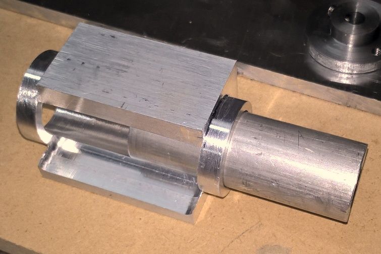
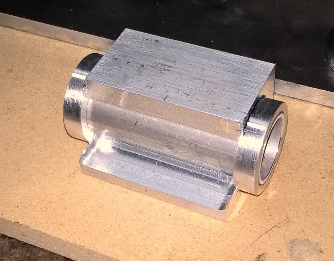
This small engine is designed after a horizontal mill-style steam engine. It's powered by two, hand-wound magnetic coils driving a piston assembled from 3 or 4 neodymium magnets.

https://youtu.be/oJf7N7hsLk4

The coils are attached to an Arduino micro controller with a motor shield. The valve rod on the engine pushes against a small micro-switch turning it on for half a revolution and off for the other half. The Arduino, sensing whether the switch is on or off, alternately reverses the current through the two coils.

The engine is double acting. In both directions, one coil is pushing on the magnetic piston while the other coils is pulling. Reversing the current at the end of each stroke reverses which coil is pushing and which is pulling. Here is a schematic showing the operation.

Solenoid_zpszd9vvorg.jpg


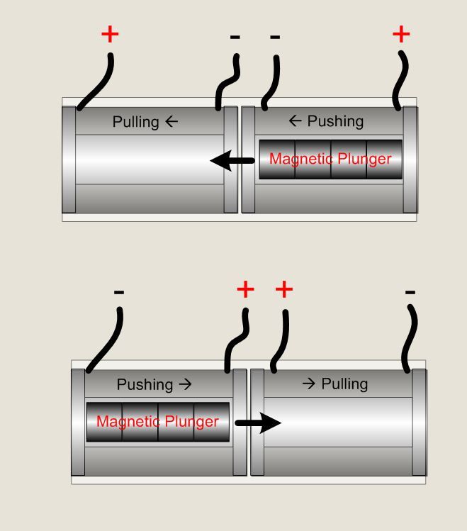
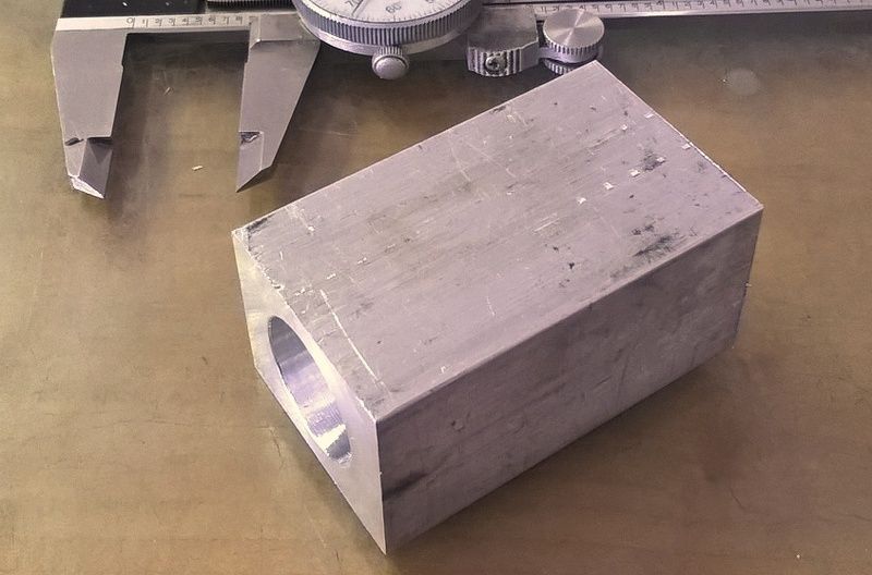
If there is sufficient interest, I'll post pictures and descriptions from the build process.

Chuck
 
Hi Chuck,

I have really enjoyed you solenoid builds over the years, but surely, when you have to go to Arduino control, it is going beyond what most people would like to build themselves, except for a very few who are into that side of things.

But anyway, having looked at your video, I noticed a weak spot. The micro switches. If you are using such a complicated running setup, I would have thought you would have used a simple contactless switch setup as micro switches have a very limited life of only about 3million operations, often a lot less, soon reached if the engine is run say as a display at a show.

Sorry to have been so negative, but you did ask.

John
 
Man, that's fantastic Chuck; it runs great, steady as a locomotive! Can't wait to see it clicking over at a slow speed when you add that function. With Arduino control, you should be able to write software for a Walter Mitty idle mode. You know, "ta-pocketa-pocketa-pocketa-pocketa-pocketa":thumbup:

Seriously, that is so cool; you must be very happy, I know I would. Congratulations!

(And yes, please post every detail!)

Thanks for the comments! I'll continue to post pictures and information about the build.

Chuck
 
Hi Chuck,

I have really enjoyed you solenoid builds over the years, but surely, when you have to go to Arduino control, it is going beyond what most people would like to build themselves, except for a very few who are into that side of things.

But anyway, having looked at your video, I noticed a weak spot. The micro switches. If you are using such a complicated running setup, I would have thought you would have used a simple contactless switch setup as micro switches have a very limited life of only about 3million operations, often a lot less, soon reached if the engine is run say as a display at a show.

Sorry to have been so negative, but you did ask.

John

Hi John, thanks for your comments. I had considered using a hall affect sensor since I have used those successfully on other projects. However, I went with the micro switch for expediency. I have a bunch of them on hand and it's easy to replace if it wears out.

I built this engine because I wanted to keep it on my desk at home to look at and run occasionally. So, it was important to me that it look very much like a model steam engine, both sitting and running. I agree, it's more complicated than most folks would want to undertake. However, I wanted to expand my knowledge and experience with solenoids and Arduino circuits and programming, so, yeah, it's kind of a 50 cent solution to a nickel problem.

Chuck
 
I do understand where you are coming from Chuck, I will have to go through the same learning curve sooner rather than later with regards to wiggly amps and electric string.

You just keep up the good work as you are the one I always watch for something new in model engines.

Your development of the vapour carb was astronomic, it changed Jan Ridders one into something that can be used by everyone. I see that some US folk are using the same principle on their trucks to get massive mileages out of a gallon of fuel.

John
 
Here's some more on the build of this engine. The solenoids are totally enclosed in the bore. I started with a 2.5" x 1.5" x 1.25" block of aluminum. After truing it up, I bored a .875" hole through the center.

WP_20160312_16_25_30_Pro_zpsgmqzfz4n.jpg


Next I turned a 1.125" x .25" boss on each end.

WP_20160312_16_43_15_Pro_zpsqaqh6ndu.jpg


Then I milled out one side to expose the bore and leave a foot on the bottom for attaching the cylinder to the base. I will be milling an identical pocket on the opposite side. Here are two pictures from different angles.

WP_20160312_20_43_23_Pro_zpsrihu3taa.jpg


WP_20160312_20_43_40_Pro_zpszktsmqjg.jpg


I will be loctiting a sleave in the bore to house the solenoid.

WP_20160312_20_43_59_Pro_zpsipskxj6m.jpg


WP_20160312_20_44_08_Pro_zps2mxgkslb.jpg


I still need to mill the pocket out of the other side and do some finish work on the cylinder before I count it finished.

Chuck
 
Here's another video showing the more or less finished engine...

https://youtu.be/i_eC_M0FsTs

I built a base out of maple hardwood and steel columns to support the engine. The Arduino Uno and it's motor shield are permanently attached to the base. The potentiometer is a temporary arrangement and will be permanently mounted soon. I'm using the potentiometer as a voltage divider which lets me provide a variable voltage to one of the Arduino's analog input pins. In "Full Throttle" mode, the Arduino switches off the coils at the end of each stroke, reverses the polarity, then immediately turns the coils back on at full power. To control the speed, the Arduino sketch is using the potentiometer value to introduce a variable delay between the end of each stroke and the re-energizing of the coils for the next stroke. The maximum delay in this video is about 100 milliseconds. It will continue to run with a 125 millisecond delay but operation gets a bit jerky. With a delay any greater than 125 milliseconds, the engine stops about half way into the next stroke, then restarts when coil is energized. Theoretically, the engine will run at 1 revolution per hour or even 1 revolution per day, but it would merely stop for half an hour or half a day, then move half a revolution, then stop again.

I tried reducing the power by running the PWM at less than 100%, but I got an annoying whistle which I assume is from the frequency of the Arduino PWM, or perhaps a beat frequency between the two coils since each is running on a separate PWM pin. At any rate, I feel like the delay mechanism is quite satisfactory.

I will continue to post pictures of the build process.

Chuck
 
That turned out very well. I like it. I also like your complete explanation of how it works.

I can see the pot. set up with some sort of calibrated dial plate in an early-20th-century style.

Thanks for posting

--ShopShoe
 

Latest posts

Back
Top