Small V8

Home Model Engine Machinist Forum

Help Support Home Model Engine Machinist Forum:

This site may earn a commission from merchant affiliate links, including eBay, Amazon, and others.
Metal Mickey said:
Could you annotate any picture if its done by CNC? Take it as a compliment about telling the difference!

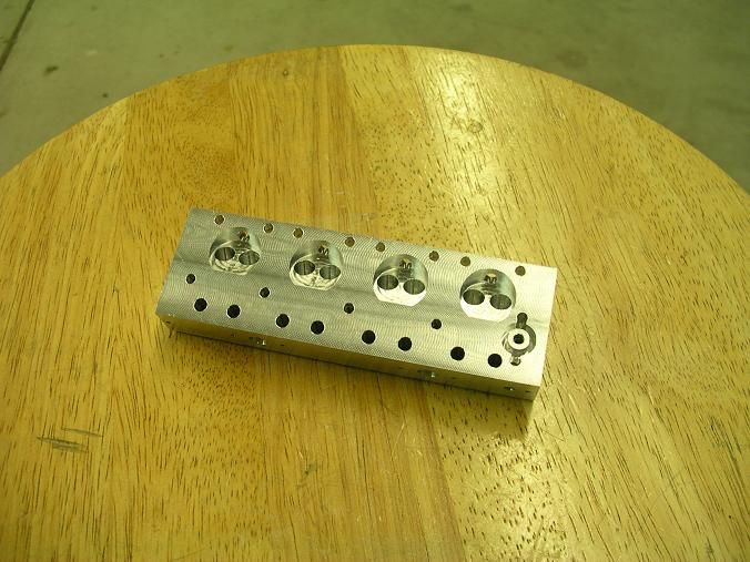
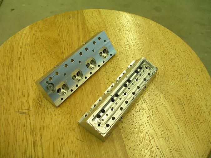
Great to hear from you Mickey. This whole mess was done in Alibre. As for the CNC, Look at the photo of the combustion chambers. The bottom of the head was done manually and the chambers were CNC'ed. You can tell the differance just looking at them.

Hope your health is good!!

Steve
 
Hi Steve,

I enjoy watching your V8 taking shape and boy are you flying along.

When you CNC'd the oil pan, did you do some roughing on the manual mill, the inside cavity for example, or did you let the CNC do all the work? If you have any photos of the fixturing and machining for the oil pan, you might post them. I'd like to see how you held the material.

Regards,

Chuck Kuhn
 
stevehuckss396 said:
The bottom of the head was done manually and the chambers were CNC'ed. You can tell the differance just looking at them.

Steve

Thanks Steve, I see what you mean. Will follow your work with great interest including the drawing if you include it.

Great work as always.
 
kuhncw said:
When you CNC'd the oil pan, did you do some roughing on the manual mill, the inside cavity for example, or did you let the CNC do all the work? If you have any photos of the fixturing and machining for the oil pan, you might post them. I'd like to see how you held the material.

Sorry no pictures.
I grabbed a block in the vise and cut the bottom from the oil plug boss all the way down to the rim where it bolts to the block. Then I just flipped it over and grabbed it in the vise again and did the top rim and inside and the blot pattern from the top. Yes I did rough the center out on the big mill. Then the CNC mill just cut the last bit out and the last .025 on the bottom.
 
Today I managed to get the pockets for the valve cages cut in. I'm hoping to get the exhaust ports drilled tomorrow and the intake ports done over the weekend. That will complete the heads as far as cutting. Then I will spend a few days threading the many holes i have made. I also have the block back from the welder so i begin to make progress on that when the heads are done.

DSCN2172s.jpg


DSCN2176s.jpg
 
Ambitious build, Steve, but your progress so far is pretty impressive. Very nice work.

Chuck
 
That head looks great Steve. So much in a small space. :bow:

Kel

 
Not much to report other than the exhaust ports are drilled in. I need to get a set of angle blocks so i can drill the intake ports in at exactly 21 degrees. Won't be any action until Monday. Youngest son graduates from HS tomorrow and the party is on Sunday.
 
Steve, I got a couple questions.
What was your setup to cut the angles for the heads, if you currently don't have angle blocks?

And I am a little confused about the water passage in the heads, is there more than the eye can see?

Kel
 
kcmillin said:
Steve, I got a couple questions. What was your setup to cut the angles for the heads, if you currently don't have angle blocks?
And I am a little confused about the water passage in the heads, is there more than the eye can see?

I have a vise that swivels but the head is to long to be held long ways. The vise wont open far enough. If i get a set of blocks I can just use my normal milling vise and use the blocks to tilt the head. I'll get a picture of the head when I drill the intakes. I am being extra careful because when I drill, the intake hole will miss the pushrod hole on one side and the head bolt hole on the other side by .030.

The water passage is just there to allow the coolant to flow out of the block and into the intake manifold. The idea is to have the water flow in a "standard appearing" route. The coolant will enter the pump and flow down the odd bank of cylinders. It will flow thru a passage in the bell housing adapter and back down the even bank. From there it will exit the block and flow thru the head and intake manifold and out a thermostat housing and back to the radiator. Should look like the real deal.

untitled3.jpg
 
Thanks for the explanation Steve. Sound like a pretty good plan to me.

Kel
 
kcmillin said:
Steve, I got a couple questions.
What was your setup to cut the angles for the heads, if you currently don't have angle blocks?


Hi Kel!

I snapped a few pics that will further help to understand what i did here.


Every angle I needed to cut and drill allowed me hold the part in the angle vise like this.

DSCN2178s.jpg


The intake ports needed to be drilled where the head would need to be tilted like this
But as you can see my vise wont open far enough.

DSCN2179s.jpg


So I purchased a set of angle blocks si i could tilt the heads to exactly 21 degrees in my standard vise.
I hope this helps.

DSCN2180s.jpg
 
Thanks For the pics Steve.

And Wow, I had a hard time designing a V4 steamer that big and you got a hole V8 4cycle head in the same space. The pic with your hand was very helpful in determining scale.

Kel
 
kcmillin said:
And Wow, I had a hard time designing a V4 steamer that big and you got a hole V8 4cycle head in the same space. The pic with your hand was very helpful in determining scale.

Yeah man! I think I started on them last Saturday so they were alot of work/time. I am happy with them. Everything is within a few thou and most times closer. The scary part is drilling the ports and not hitting a hole. They only miss by .035 or something like that. There is alot packed onto that little block of aluminum.


Only a year to go!!

 
Excellent job Steve. I ran into a similar problem when making my 302 heads. What I ended up doing was to make the port the correct size, which ran through the pushrod hole, then made the pushrod hole over sized and sleeved it back down. This gave me my port capacity while still fitting it in the small space. Is this engine going to be pressure oiled, if so I can tell you how I set mine up.
George
 
gbritnell said:
Excellent job Steve. I ran into a similar problem when making my 302 heads. What I ended up doing was to make the port the correct size, which ran through the pushrod hole, then made the pushrod hole over sized and sleeved it back down. This gave me my port capacity while still fitting it in the small space. Is this engine going to be pressure oiled, if so I can tell you how I set mine up.
George

I'm going to make it splash like the Peewee. The crankshaft is very small and I think drilling holes would be a bad idea. The bad part is that the valve covers will need to be taken off once in a while to lube the rockers.

Of course it wouldn't hurt to look at what you have for future projects!!
 
Back
Top