Small model V8 motor built at home scratch built

Home Model Engine Machinist Forum

Help Support Home Model Engine Machinist Forum:

This site may earn a commission from merchant affiliate links, including eBay, Amazon, and others.

dixon

Member
Joined
Apr 30, 2010
Messages
22
Reaction score
0
Started off with a piece of 4" aluminium about 12 long and it all stemmed from there.

Here is a few pictures of the build up process and a video of the finished product. This is the first model I have built.

02052011.jpg


04062011001.jpg


13082011.jpg


01052011003-1.jpg


15052011001.jpg


24042011006.jpg


29052011007.jpg


Yes!! Definitely keep us posted. Great work indeed.

Ron
 
You picked a helluva project for your first build - impressive.

Can't wait to see more.

Ken
 
[ame]http://www.youtube.com/watch?v=ZlCWbpqTXS8[/ame]

here is my video

i have a lot more photos step by step progress if anyone is interested


If we are interested? Silly guy, ;D of course we are interested.

Post away.

Is that PVC couplers and copper elbows for an intake manifold?

Ron
 
Grest engine and nice looking parts. Thanks for sharing!
 
What a great looking and sounding engine!

Looking forward to seeing more pictures... can't get enough of them ;D
 
Hi Dixon,

We are absolutely interested in your wonderful project !!!

th_wwp th_wwp

Cheers,

Alexandre
 
nice job mate
Pete
 
WOW!!! When I think of a first project I think of a small wobbler or a single steam engine. BUT an eight cylinder internal combustion engine? WOW!!!

That is incredible and you have my admiration.... Wish we had seen the build...

Keep up the good work.

Harold
 
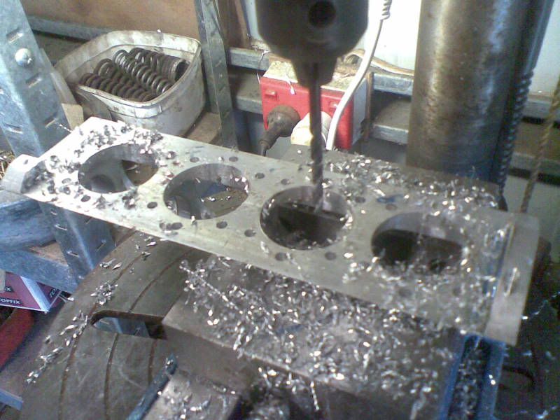
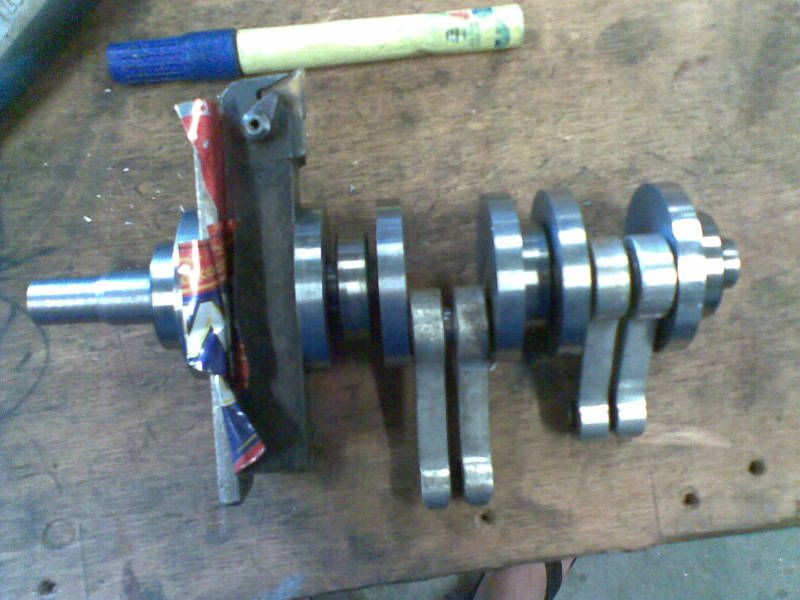
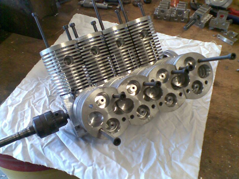
ok my daughter has done all the computer stuff the digital readout on my little lathe is enough for me i am just learning how to text we will see how we go with this the firing order of this little engine is 12478356 number one is left hand side front number two is right hand side front so 1357 on the left and 2468 on the right . notice full stop. im learning. the firing order could have been a few different ways including 12345678 but i thought i had better spread it around as much as i could. the bore is 1.250 and the stroke is 1.187 .the stroke ended up that size because that was as close to the bore size i could get by putting the jaws in the three jaw in the wrong order . because i had to copy these sizes numerous times. the crank has ball bearing mains 15 mm id x 5 and big ends are needle rollers 12 mm id 90 degrees apart starting from front of crank , not like a couple of other throws that i have seen ... but this isnt where it all began, maybe this can be chapter one ...time here is 7.30 pm aest
aust time
 
ozzie46, the inlet manifold is made of 5/8 copper elbows and tees (i painted them to hide my ugly silver soldering)
 
dixon said:
http://www.youtube.com/watch?v=ZlCWbpqTXS8

here is my video

i have a lot more photos step by step progress if anyone is interested

what would make you think we would be interested in step by step pictures........ :p :p
we are not really interested, WE LOVE THEM!!!!
post them up so we all can drool over them :bow: :bow: :bow:
pascal
 
22042011.jpg


22042011001.jpg


22042011005.jpg


22042011006.jpg

this is the piece of ally i started with. i bored a hole through it ,cut it in half length ways, put two hose clamps around it so i could grab it in the chuck to put two steady tracks on it . then i drilled and taped 4 m6 holes so i could bolt it together and remove the clamps . then i machined all the main bearing diameters and spaces for the crank counterweights. lots more to come
 

Great engine Dixon!

I like your approach to the crank case. It will be interesting to see the rest.

 
Awesome work on the engine Dixon, it sounds great!!

Keep the pictures coming.

Kel
 
Back
Top