- Joined
- Jul 16, 2007
- Messages
- 2,979
- Reaction score
- 1,046
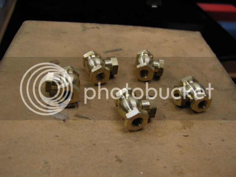
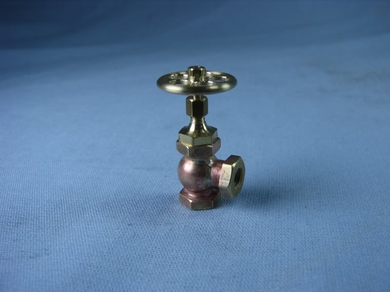
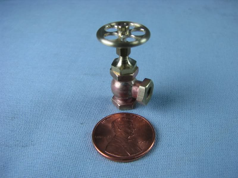
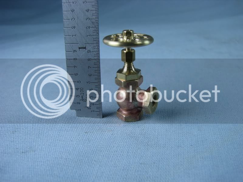
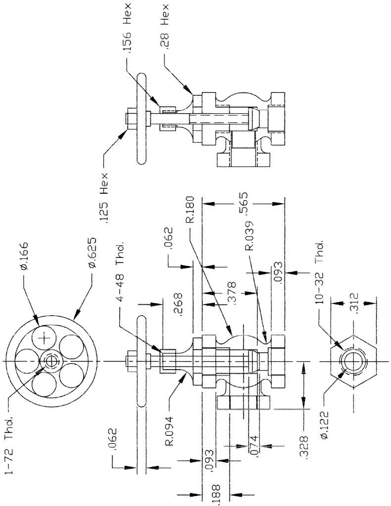
Gentlemen,
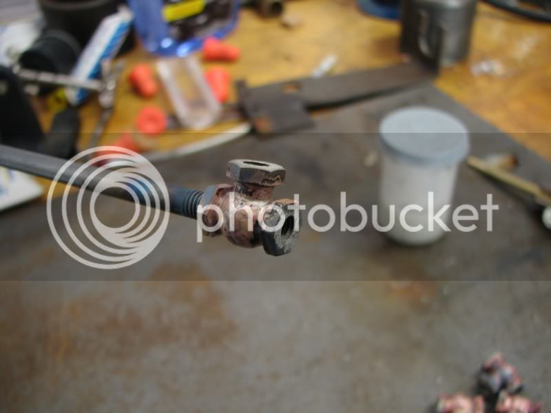
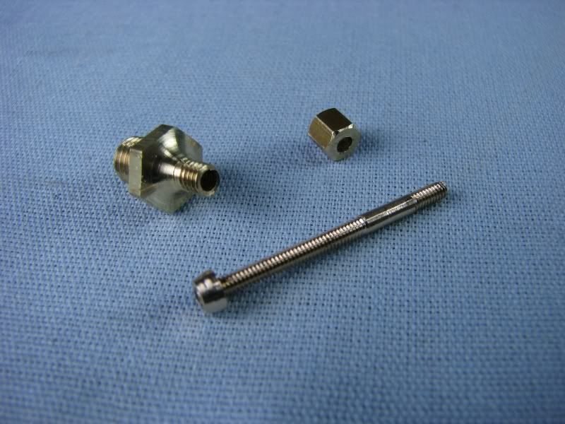
When I attend model engine shows some of them supply compressed air for the steam models, or air models as the case may be. For years I have had a little brass manifold with some aquarium valves on it. It works well enough but I decided I needed to class it up with some new valves, so five new ones were in the works. I know it's not a complicated build like making an engine but thought that there might be some who could gain from a photo essay. I started out drawing out what I wanted on AutoCad and then headed for the shop. First up would be the valve body. It would need to be a fabrication because of the shape. I have quite a few high speed steel forming tools that I have made over the years but I didn't have one for the body of the valve so I ground up another. I first roughed it on my bench grinder then with a small mounted stone in my Dremel I cleaned up the radius, matching it to my radius gauge. First I turned the .50 brass stock down to .36. Why not use .375 stock? I find that when using a forming tool everything needs to be as ridgid as possible, stock and tool, so I like to use larger stock to eliminate any chatter.
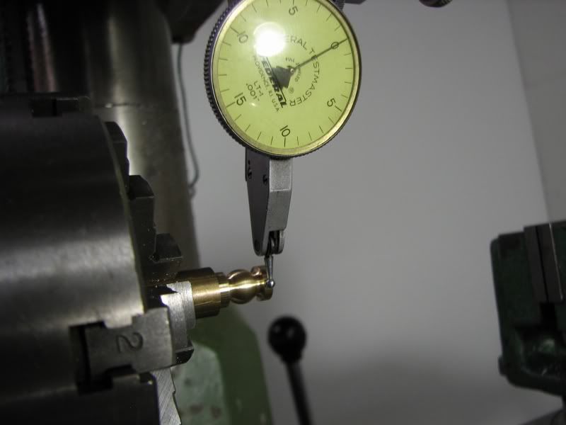
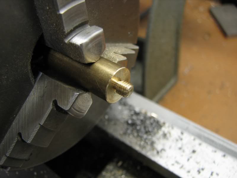
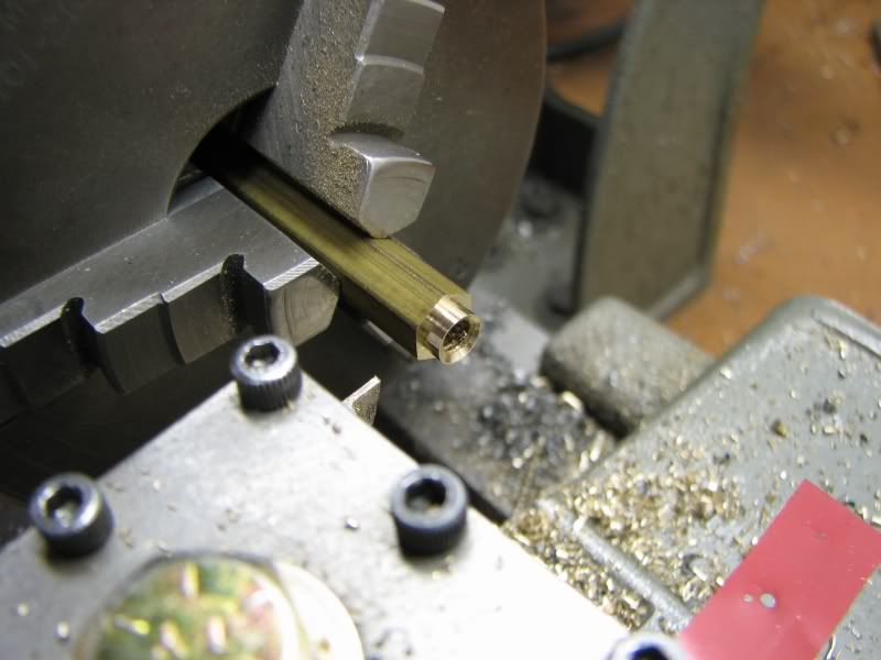
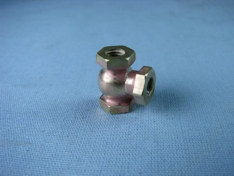
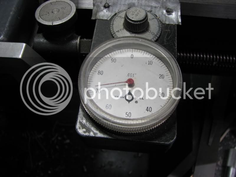
I then put in my small radius tool to do the blend radius at each end. I have a Trava-dial gauge on my lathe so I touched off to the end of the stock and moved over the required amounts, plunging in to the needed depth
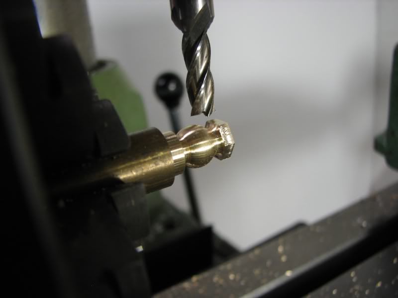
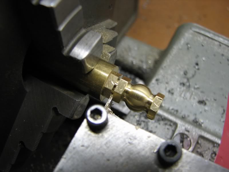
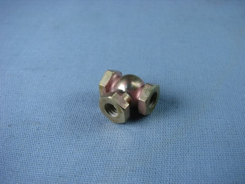
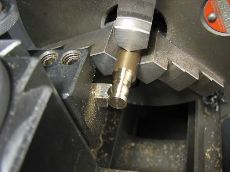
Then came the body forming tool. It is a .18 radius. I find that you want to go to your depth and as soon as you get there back out before it sets up a chatter. You can eliminate the chatter by slowing down the lathe but with my Logan that means shifting the belts so I have good luck this way.
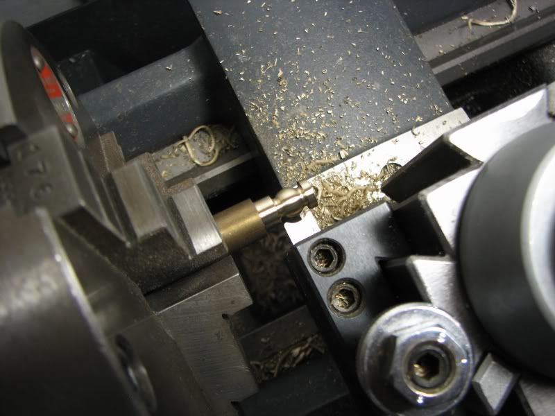
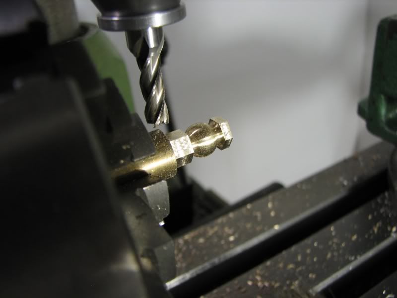
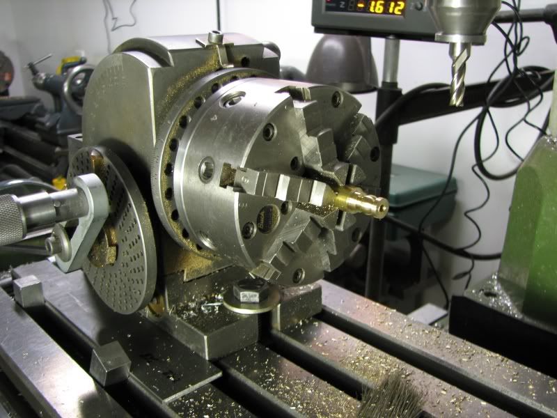
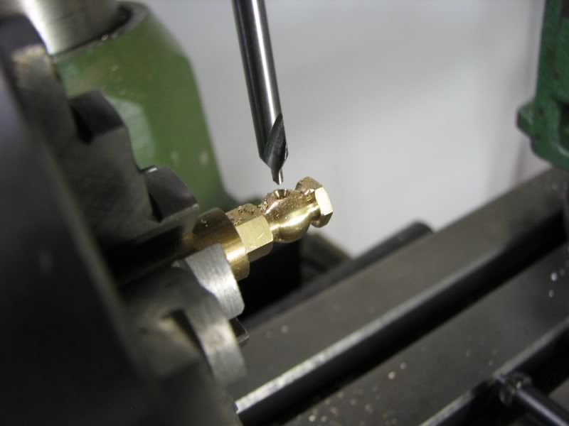
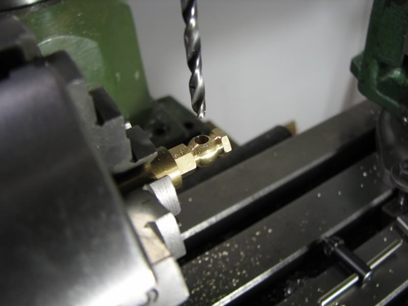
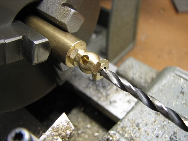
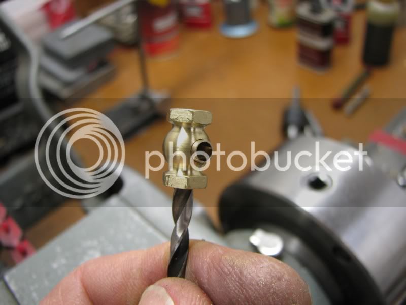
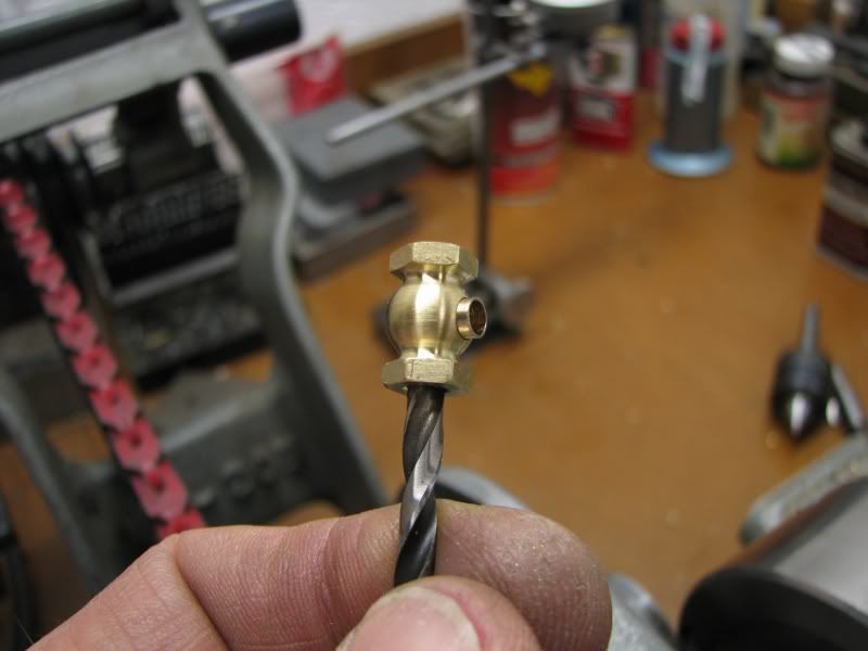
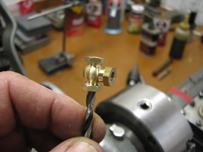
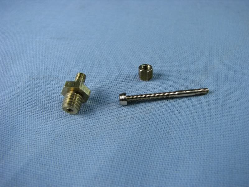
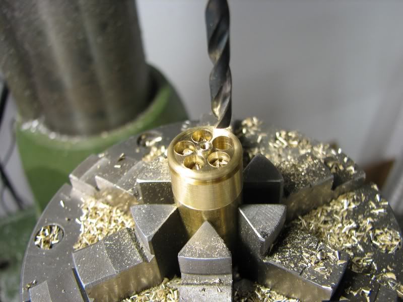
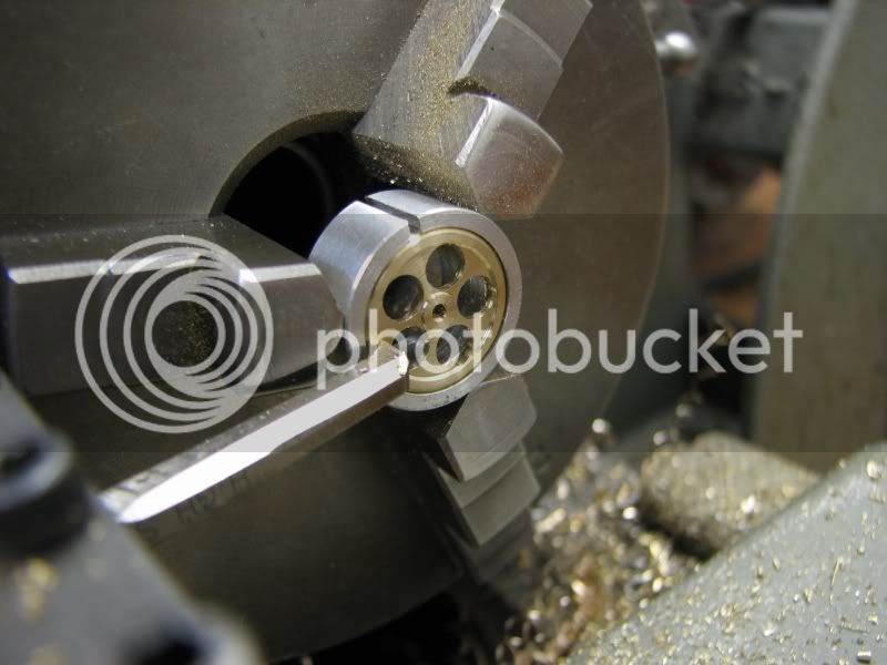
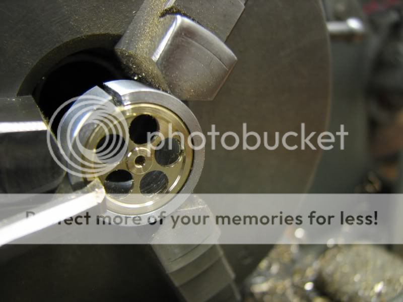
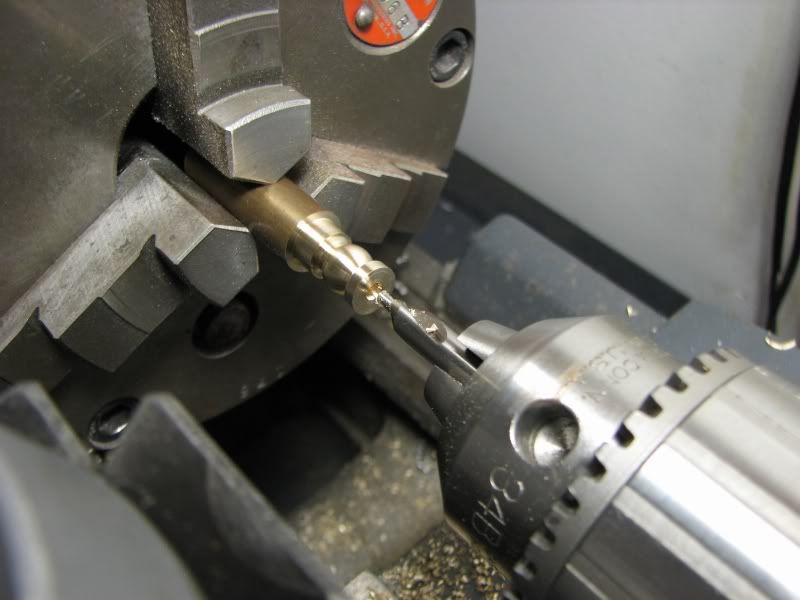
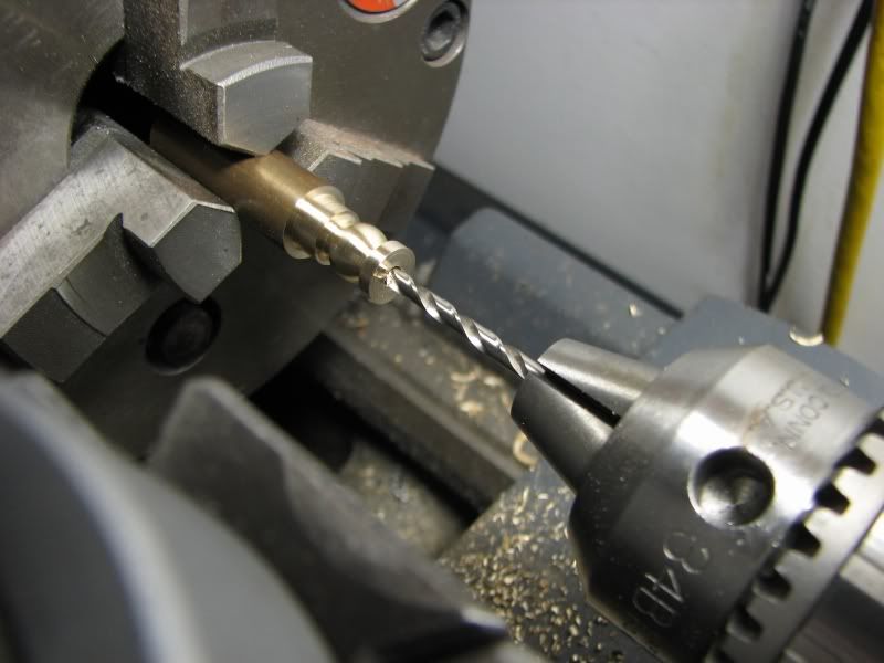
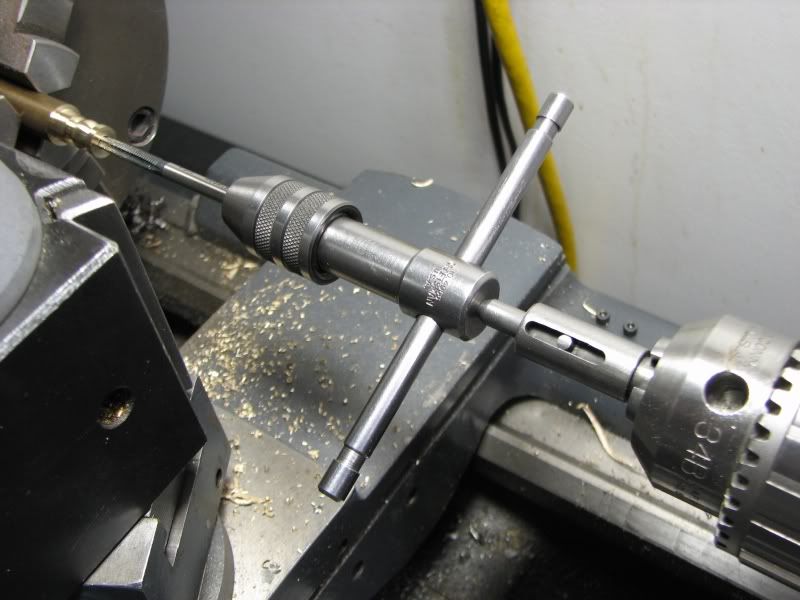
Next came the drilling and tapping for the for the valve spindle tower. Not much explanation is needed here, just a couple of pictures.


When I attend model engine shows some of them supply compressed air for the steam models, or air models as the case may be. For years I have had a little brass manifold with some aquarium valves on it. It works well enough but I decided I needed to class it up with some new valves, so five new ones were in the works. I know it's not a complicated build like making an engine but thought that there might be some who could gain from a photo essay. I started out drawing out what I wanted on AutoCad and then headed for the shop. First up would be the valve body. It would need to be a fabrication because of the shape. I have quite a few high speed steel forming tools that I have made over the years but I didn't have one for the body of the valve so I ground up another. I first roughed it on my bench grinder then with a small mounted stone in my Dremel I cleaned up the radius, matching it to my radius gauge. First I turned the .50 brass stock down to .36. Why not use .375 stock? I find that when using a forming tool everything needs to be as ridgid as possible, stock and tool, so I like to use larger stock to eliminate any chatter.
I then put in my small radius tool to do the blend radius at each end. I have a Trava-dial gauge on my lathe so I touched off to the end of the stock and moved over the required amounts, plunging in to the needed depth
Then came the body forming tool. It is a .18 radius. I find that you want to go to your depth and as soon as you get there back out before it sets up a chatter. You can eliminate the chatter by slowing down the lathe but with my Logan that means shifting the belts so I have good luck this way.
Next came the drilling and tapping for the for the valve spindle tower. Not much explanation is needed here, just a couple of pictures.