


Being a new member I thought I might bring you up to date with a few projects I had done previously. This was one of those, "I need it right now for my dissertation" projects. My daughter needed a Sieve shaker for her studies at Oregon State University.
A sieve shaker is a series of screens stacked so that the particles are sorted out from the largest to the smallest when shaken in water. Then the components are emptied out, weighed and recorded to determine soil characteristics.
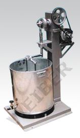
We did our research on the web and this is what we typically found. Large and expensive (around $4,000), current models were made for the largest labs. We decided that was an overkill so we found the specified length of throw and the reciprocating frequency and off we went. I decided to build a lighter and more portable version (one with a guard, too).
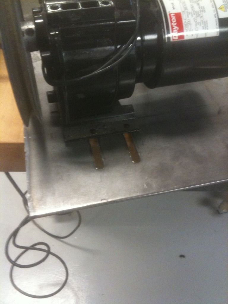
Fortunately, I had a Dayton gear motor around and I designed it from there. Starting with a 1/4" plate, I laid out the motor location making slots for adjustment.
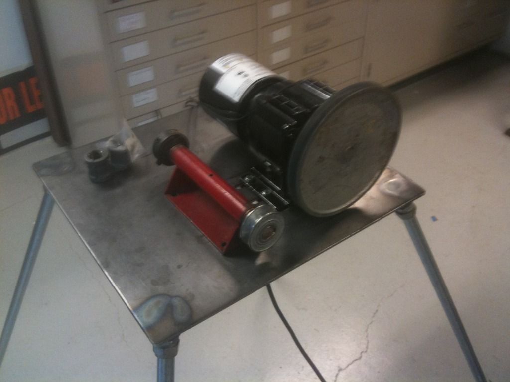
I found an old jackshaft lying around that would work with some modification. For the legs I used 1/2" conduit with some compression 1/2" conduit fittings. I found some heavy duty 1/2" couplings that I cut on an angle and welded to the bottom corners of the plate. The conduit tightened in nicely giving the option of removing the leg by either threading them out or loosening the compression fittings.
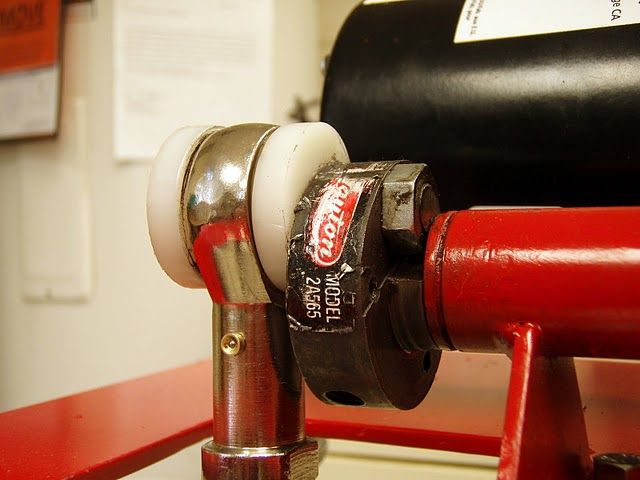
The next step was to develop the crankshaft. Using the old jack shaft I bought some dayton bronze bearings and inserted them in each end of the old jackshaft. I drilled a small hole in the top for lubrication. I had a pulley center (Dayton that would attach to the shaft). I turned it on the lathe to smooth the face and then drilled it 3/4" off center to give the desired 1 1/2" stroke. I ordered an link end to form the connecting rod. I threaded the hole for the shaft in the turned pulley center and double nutted it to secure it. Finally I turned modified two plastic washers to keep the crankshaft running true.
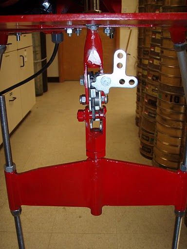
I needed to connect the end link to the sieve frame. I found a quick release in my hardware pile, turned a piece to match up and fabricated the spreader piece. This allowed a quick disconnect to remove the sieve screens.
Figuring the correct rotation rpm, I picked up the right pulleys doing the calculations and took my best guess at the belt length (actually, I bought three to take two back. Time has taught me that lesson). I also purchased an electrical box that would serve as a belt guard and installed it. I wired it in with a timer, tightened everything up and fired it up. It had the right stroke and rpm. That left the last step, holding the sieve in place.
The sieves fit nicely in a five gallon plastic bucket. The only thing left was to set up a means of holding them in place. The all-thread rod is 3/8" stainless and I wanted something non corroding for the frames.
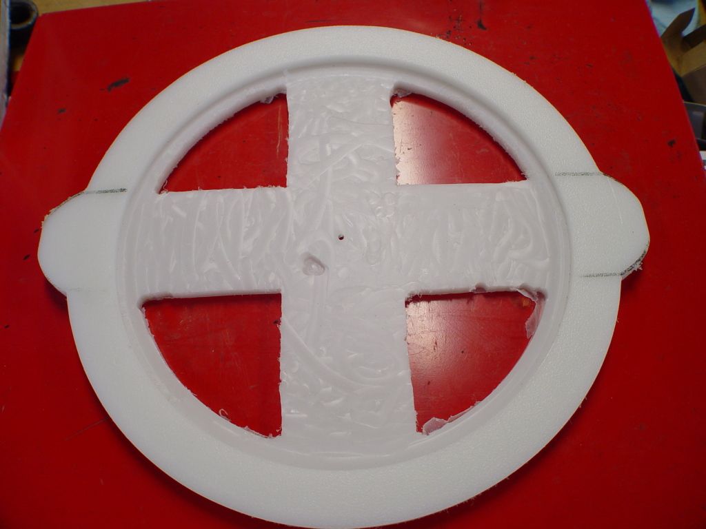
I chose 1/2" UHMW plastic for the two pieces, top and bottom, cutting them on a band saw and sabre saw and routing them out to take the sieves. This one is in process. There was a total of two, one top and one bottom.
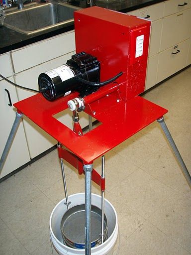
Here it is shown in the Oregon State University lab, ready to get dirty. On the end of the belt guard box you can see the installation of a timer (2 minute increments). Inside the belt guard I typed up a list of parts for future reference.
Thank you for looking at my project.
Jim
A sieve shaker is a series of screens stacked so that the particles are sorted out from the largest to the smallest when shaken in water. Then the components are emptied out, weighed and recorded to determine soil characteristics.
We did our research on the web and this is what we typically found. Large and expensive (around $4,000), current models were made for the largest labs. We decided that was an overkill so we found the specified length of throw and the reciprocating frequency and off we went. I decided to build a lighter and more portable version (one with a guard, too).
Fortunately, I had a Dayton gear motor around and I designed it from there. Starting with a 1/4" plate, I laid out the motor location making slots for adjustment.
I found an old jackshaft lying around that would work with some modification. For the legs I used 1/2" conduit with some compression 1/2" conduit fittings. I found some heavy duty 1/2" couplings that I cut on an angle and welded to the bottom corners of the plate. The conduit tightened in nicely giving the option of removing the leg by either threading them out or loosening the compression fittings.
The next step was to develop the crankshaft. Using the old jack shaft I bought some dayton bronze bearings and inserted them in each end of the old jackshaft. I drilled a small hole in the top for lubrication. I had a pulley center (Dayton that would attach to the shaft). I turned it on the lathe to smooth the face and then drilled it 3/4" off center to give the desired 1 1/2" stroke. I ordered an link end to form the connecting rod. I threaded the hole for the shaft in the turned pulley center and double nutted it to secure it. Finally I turned modified two plastic washers to keep the crankshaft running true.
I needed to connect the end link to the sieve frame. I found a quick release in my hardware pile, turned a piece to match up and fabricated the spreader piece. This allowed a quick disconnect to remove the sieve screens.
Figuring the correct rotation rpm, I picked up the right pulleys doing the calculations and took my best guess at the belt length (actually, I bought three to take two back. Time has taught me that lesson). I also purchased an electrical box that would serve as a belt guard and installed it. I wired it in with a timer, tightened everything up and fired it up. It had the right stroke and rpm. That left the last step, holding the sieve in place.
The sieves fit nicely in a five gallon plastic bucket. The only thing left was to set up a means of holding them in place. The all-thread rod is 3/8" stainless and I wanted something non corroding for the frames.
I chose 1/2" UHMW plastic for the two pieces, top and bottom, cutting them on a band saw and sabre saw and routing them out to take the sieves. This one is in process. There was a total of two, one top and one bottom.
Here it is shown in the Oregon State University lab, ready to get dirty. On the end of the belt guard box you can see the installation of a timer (2 minute increments). Inside the belt guard I typed up a list of parts for future reference.
Thank you for looking at my project.
Jim
