Shay Locomotive

Home Model Engine Machinist Forum

Help Support Home Model Engine Machinist Forum:

This site may earn a commission from merchant affiliate links, including eBay, Amazon, and others.

Dan Rowe

Well-Known Member
Joined
Feb 12, 2010
Messages
594
Reaction score
18
The subject of Shay locomotives has been my prime focus for a while now. I have drawn several Shays from the Lima Locomotive Works drawings and have made a scrap bin of failed parts.

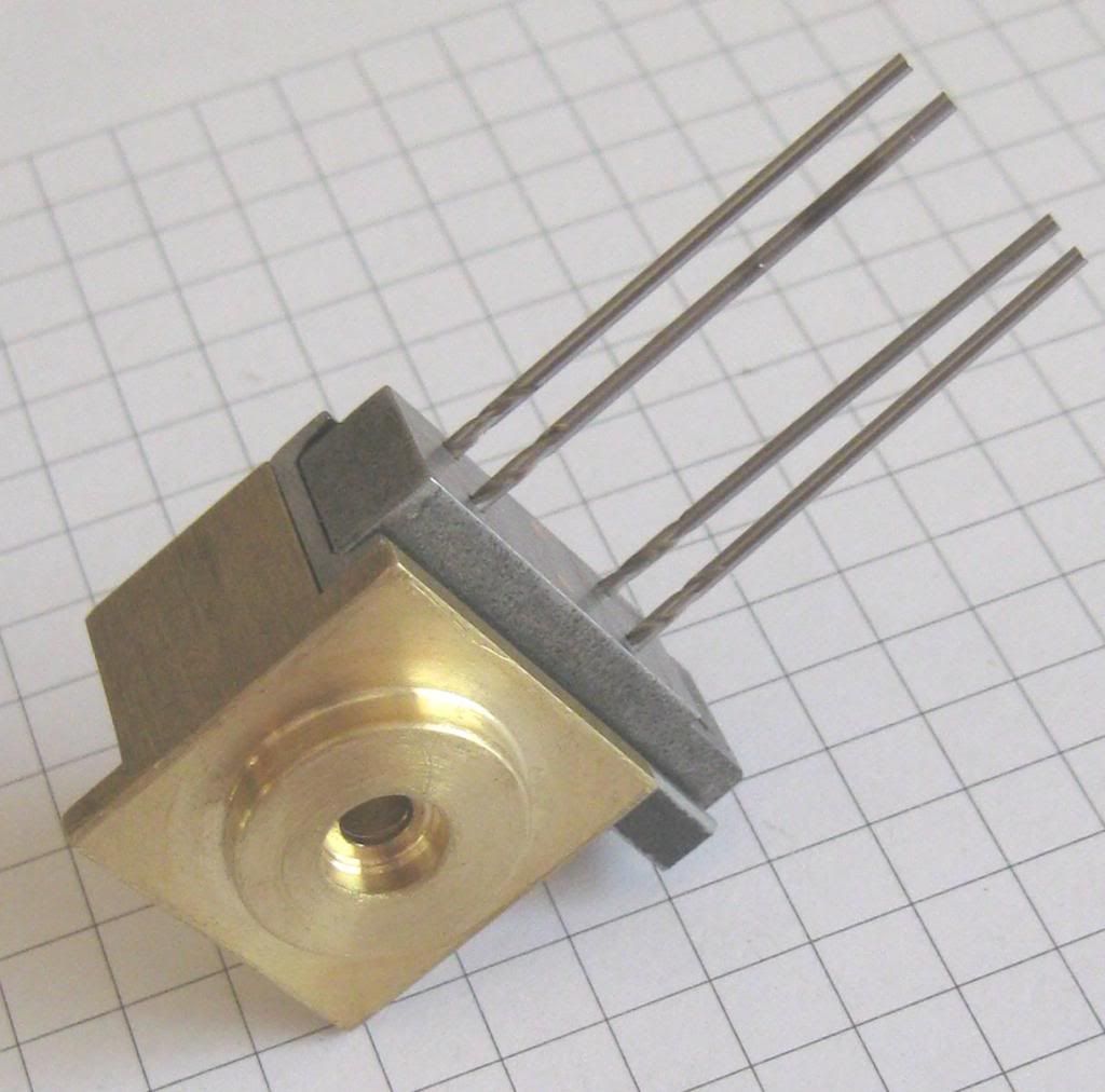
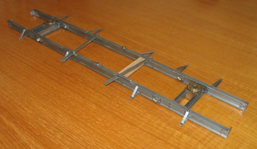
The one I am working on now is Shop Number 2800. This was a 10 ton Shay with 2-6"x10" cylinders that went to the Mapleton Tramway in Queensland Australia.
2800-R.jpg


S/N 2800 image posted with permission of the Allen County Historical Society Lima Ohio.

The scale of the build is 7/8" to the foot for G1 track. The Mapleton Tramway was a 2' line that ran in a remote area of Queensland and it serviced the comunity. The book by John Knowles "The Mapleton Tramway" covers the history of this tiny pike very well.

My drawings have been printed in "Steam in the Garden" starting in issue #100 with a double fold out showing all 4 sides in 7/8" scale. Most of the drawings in the articles are 7/8" scale versions of the LLW drawings with full size dimensions so they can be used for any scale. The next issue #114 will have the boiler prints for the two Shays used on the tramway. They had a copper fire box and brass tubes, and were built to the Board of Trade Rules.

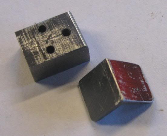
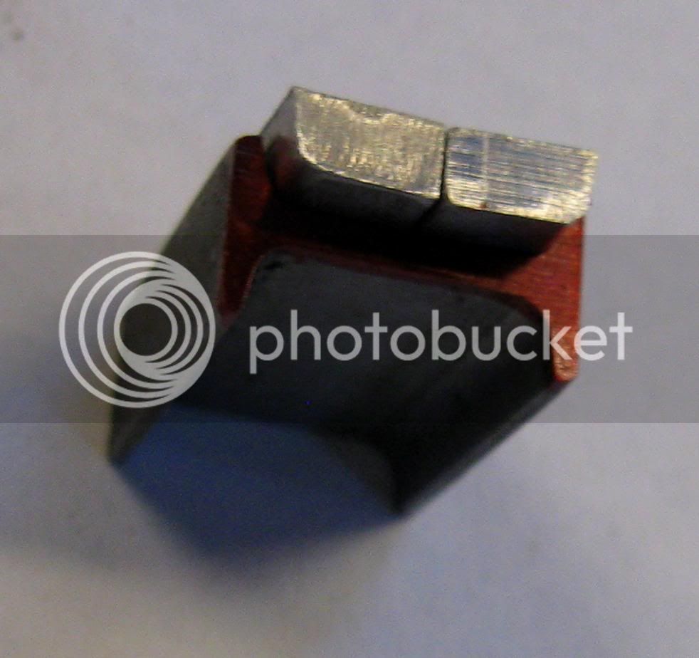
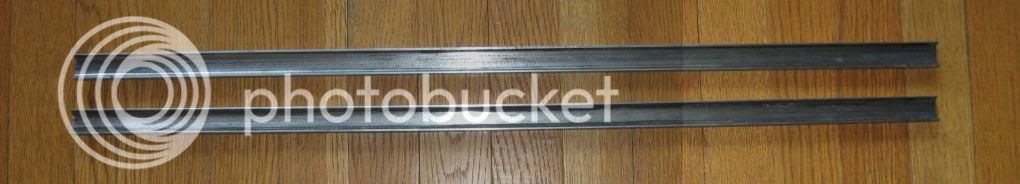
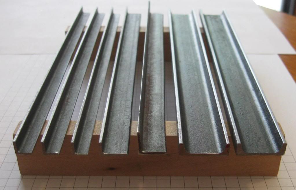
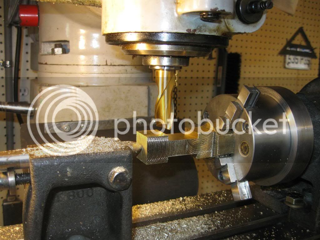
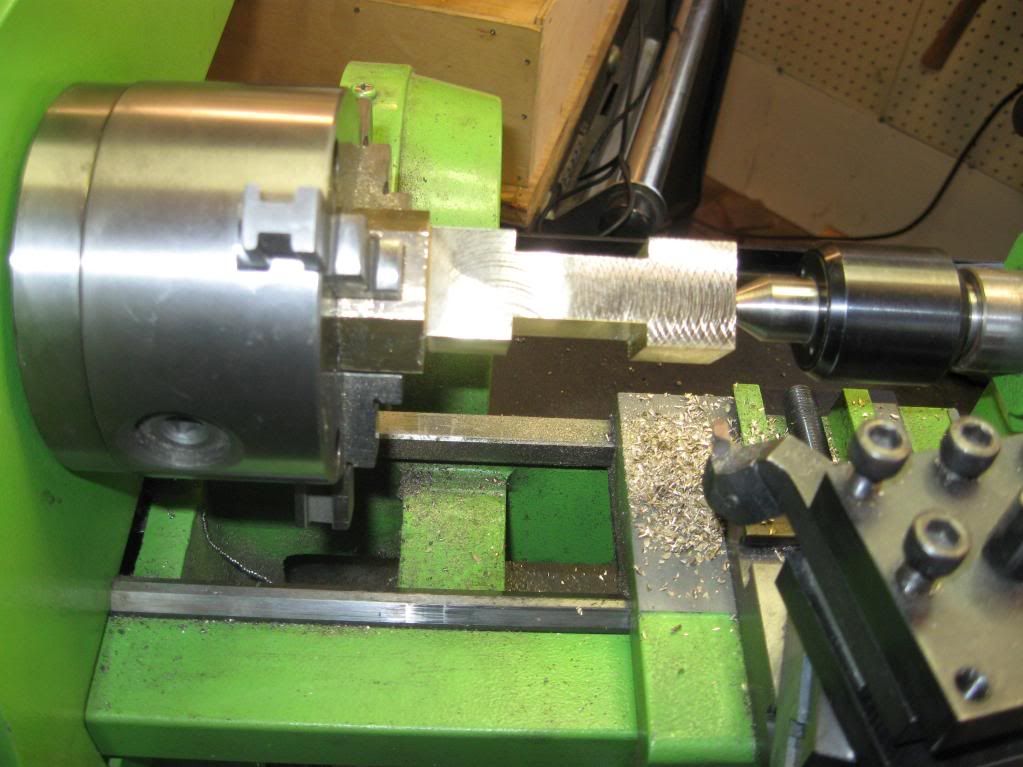
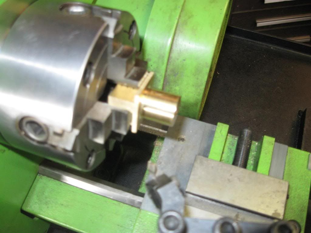
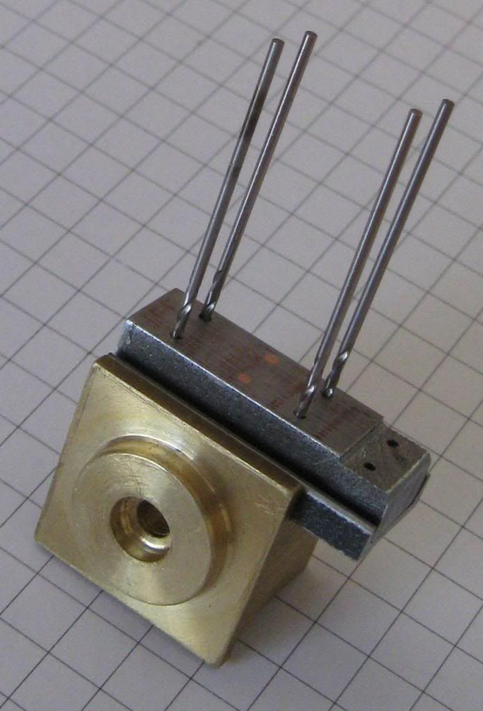
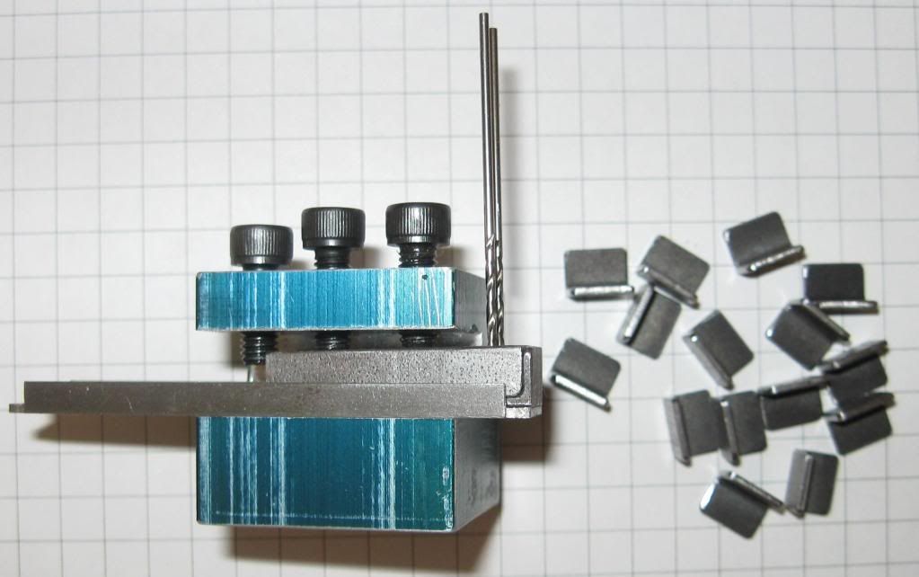
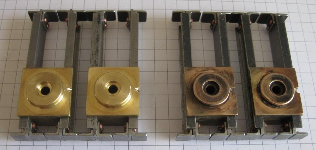
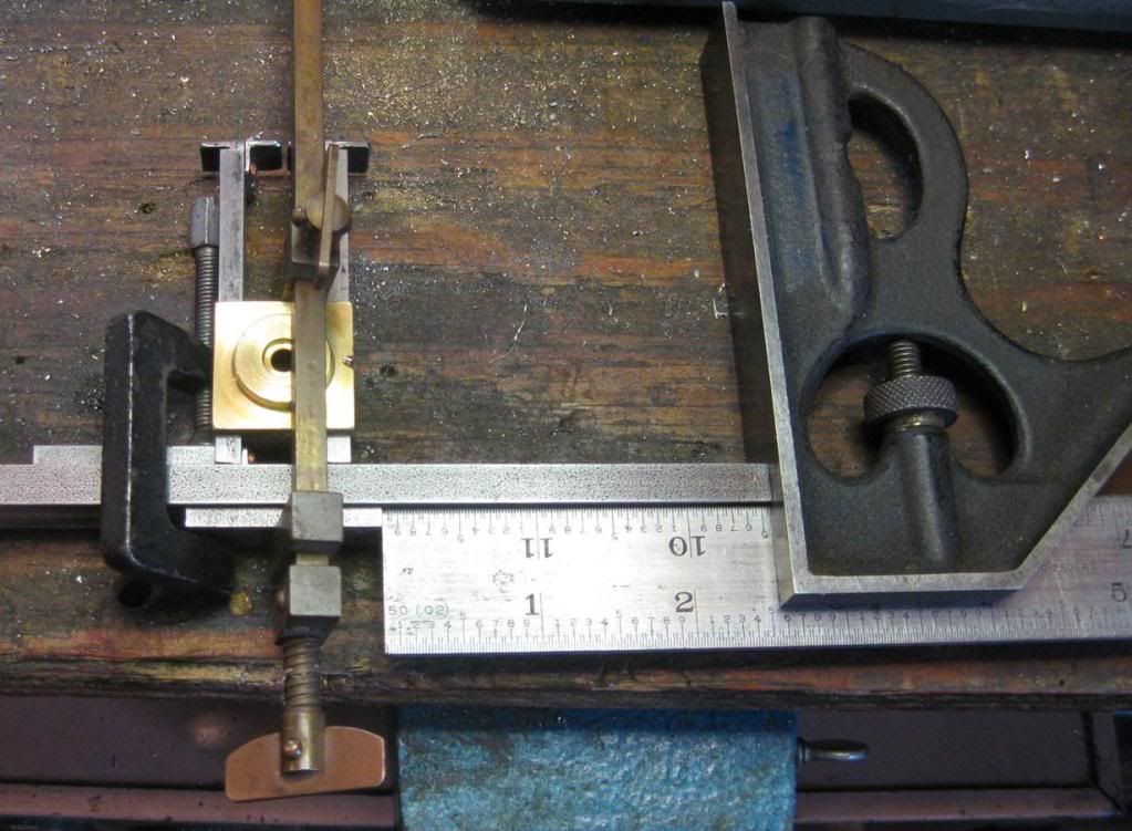
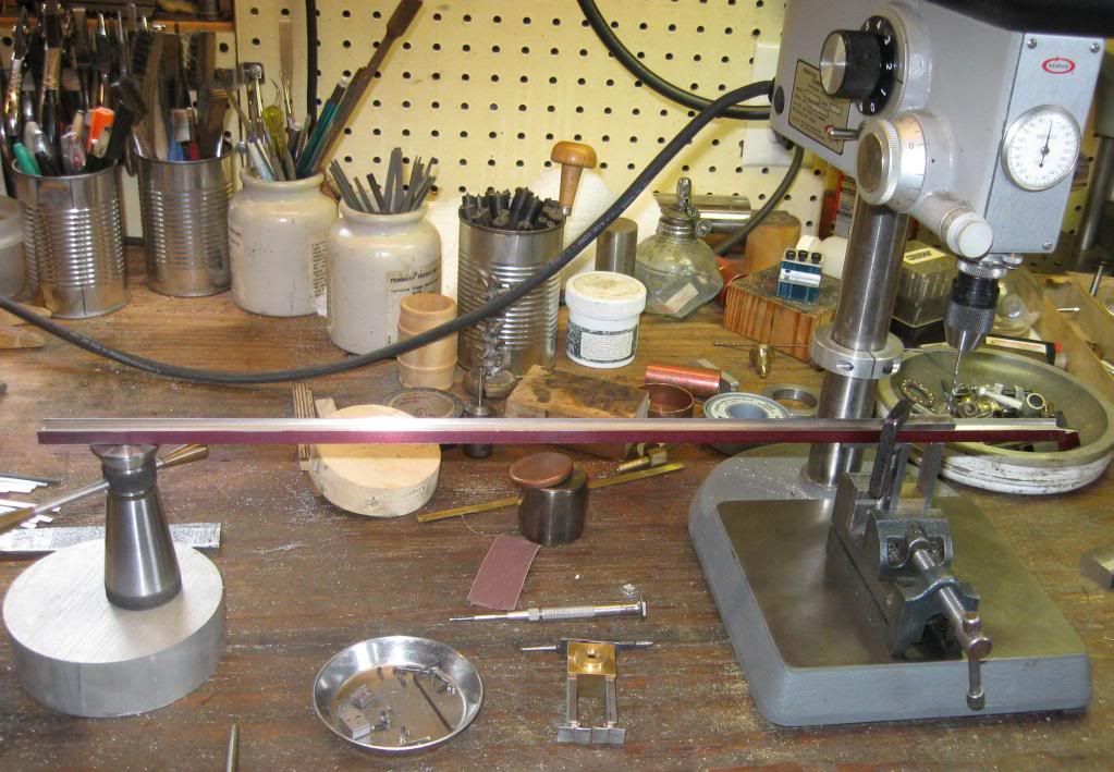
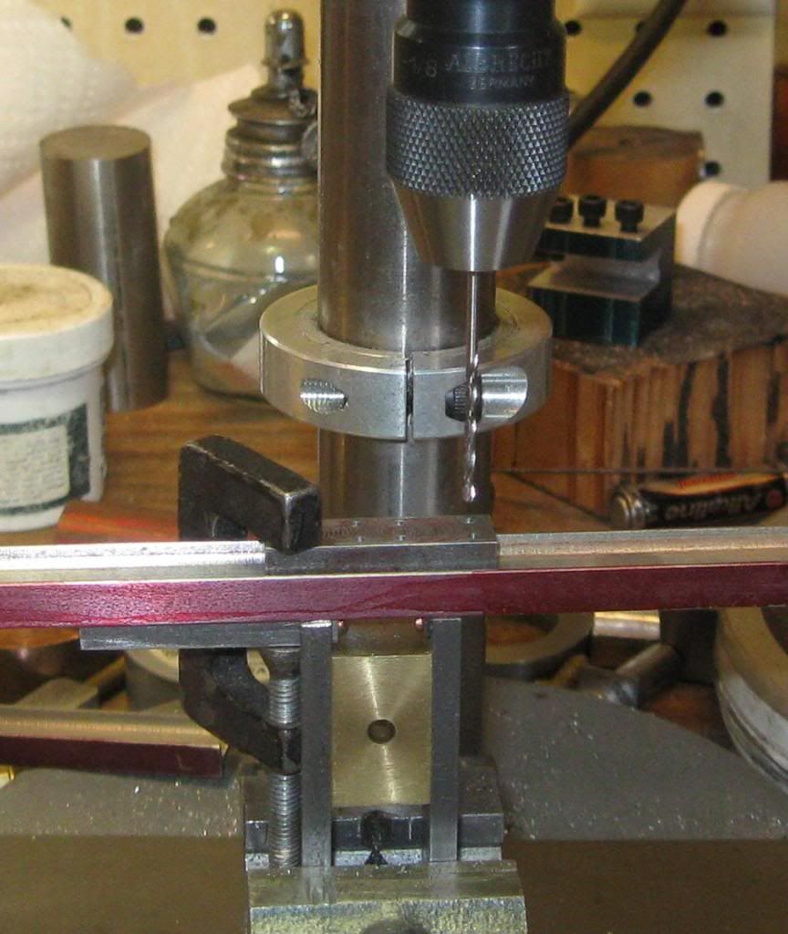
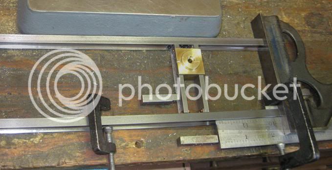
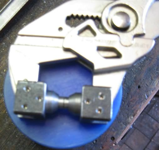
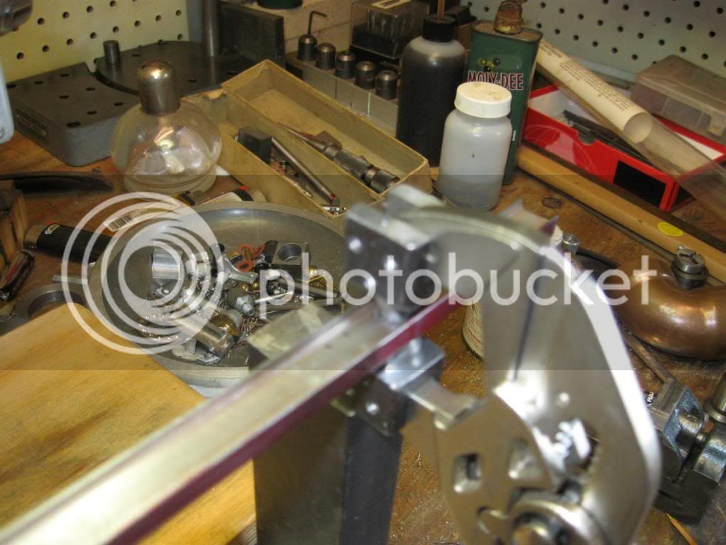
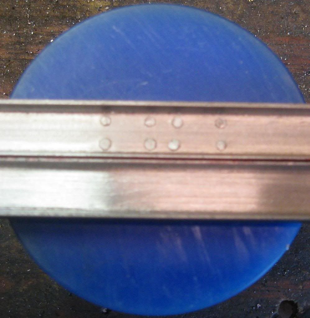
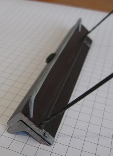
I am nearly finished with the articles and I hope to have a lot more shop time to build this Shay. The photos show my work on the frame to date.
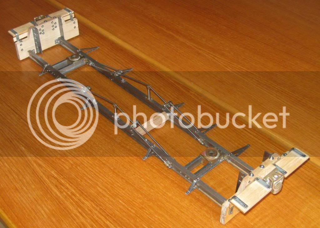
Frame02.jpg

Frame03.jpg

Frame08.jpg

Dan
 
Thanks

Here are some of the tools I made to drill and rivet the frame.
DrillJig03STRT.jpg


This is to drill the frame rail for the cross channels. There are two of them because the top one was drilled to match the LLW plan and I realized that I did not take in to account the fact that the channels I made were thicker than the original plan. The lower drill jig moves the outer sets of holes and holes now match the corner angle blocks.

DrillJig01DIAG.jpg

DrillJig01SEP.jpg


This one drills the end angles that bolt to the frame and the end timbers.

DrillJig02STRT.jpg


This one is the drill jig for the running board brackets.

DrillingRunBrdBrkt01.jpg


This is one of the running board brackets set up in a small vice ready to drill the bracket and the frame rail. Remember to drill the one with the running board bracket in it not the spare one used to keep the beam square in the vice.

BuckFrameSetupDIAG.jpg

BuckBackSTRT.jpg


This is the bucker for the rivets that hold the running board brackets. I made two small blocks that matched the profile of the frame rail, then I used the drill guide to mark the rivet location. I then used the ball end mill with a pin vice to make the recess for the rivet head.

BuckingRivets01.jpg


This shows the buckers in place set to rivet the bottom of the running board bracket.

Dan
 
That is a cute little Shay. Bring yours by the AME meeting sometime too!
 
Very nice Dan,

Makes me want to get back on my loco build. I really like the Shay. I wish Kozo's Shay books where in imperial. I am thinking of switching to one of the geared locos instead. After doing more research since I decided on the A3, I think I would rather build a loco with an attached tender to have a one piece complete loco.

Matt
 
Dan, the frame work is looking great! It reminds me of the "Climax" I started 18 years ago. I lost interest in it because of the 1/4 scale CASE I had built previous to the climax start. I was having to much fun going to the tractor shows. I sold what I had on ebay. It was about 70% complete. It finally wound up in CA someplace. I often think about and wish I had it back to complete it and see it run. I and I am sure many others will be following your progress on this build. Again, looking great !
 
Thanks for all the coments. I realized that not much really shows the scale of the build well. The frame I beam was profile milled from a 1/2" square section of 12L14 and it is 0.27" wide. The graph paper I normally set under parts to photograph has a 1/4" grid.

Here is a set of running board brackets for the Mapleton project.
RunBrdBrack-6ofEm443x468.jpg


This is the bending and drilling fixture.
RunBrdBrack-Jig-Side554x214.jpg


The top screw acts as a stop and a clamp for drilling.
RunBrdBrack-Jig-Top610x192.jpg


One of the firemans side brackets attaches to the underside of the I beam to clear the rear boiler mount. Here is the fixture modification to make the odd bracket. The top double bend with 20ga steel was a bit tricky.
RunBrdBrack-Jig-inUse686x280.jpg


This is both styles of bracket with a small section of I beam to show how the brackets attach.
RunBrdBrack-OnIbeam568x293.jpg


Dan

 
You had me at Shay! I will be watching with keen interest...
 
Hi Dan
Any more progress on the Shay?
cheers Ferd
 
Hi Ferd,
You talked me into starting the Sliver City, Pinos Altos & Mogollon RR #5 which is shop number 1928. (My drawing of this Shay is in Steam in the Garden issue #93.)

Here is the frame I did the test piece for. It is 28" long made from 1" channel cut down and silver soldered back to back.
FrameClean.jpg


Here is a bunch of hot rolled A-36 steel cut down to make the frame angles and the cross channels for the Mapleton and the Silver City Shays.
ChannelsNangles04.jpg


I am building 2 Mapleton Shays so I had to make new frame center plates. I started with a lump of 1.25" brass hex and squared it off on both ends with the mill. I used the lathe to drill a hole from both ends then I removed the chuck with the work in place and attached the 5C collet adapter so I could mill the square sections.
CenterPlateMill.jpg


Then back to the lathe to cut the round sections and leave a nice long chucking section.
CenterplateLathe.jpg


The hex piece was cut off and the rest cut in half to make both sections.
CenterplateFinishedw3jaw.jpg


Now to the 4 jaw chuck to trim the ends and add the counter bore.
Centerplate4jawchuck.jpg


A drill jig was used to drill the holes to mount the cross channels. The step section is for drilling the channels and the frame angles at the same time.
CenterplateDrillGuide02.jpg

CenterplateDrillGuide01.jpg


Here is the clamp I made to hold the channels and the angles for the drill press. Two screws clamp the work and the third one acts as a back stop.
CornerAnglesDrillFixture.jpg


Now both sets of cross channel assembles are finished for the Mapleton frames. I changed the original brass angles in the first one to steel because it looked much better and the steel does not deform with a bit of over riveting as the brass ones did.
CrossChnlCenterPlt.jpg


Dan

 
More forward progress and a bit of repair work on this project.

I clamped the drill jig using the square as a depth gauge. The brass bar clamp is just a temporary third hand. I set the clamped frame on the first unit to check the layout.
FrameDrillClamped.jpg


Drilling the frame and the cross frame assembly. I made the jack screw in advanced shop as a cadet.
FrameDrillingVistaView.jpg

FrameDrillingCloseUp.jpg


Then I set out for the second set of holes and drilled frame.
FrameDrillPreClamp.jpg


I did the third set and knocked off for the day.
I came back bright and early the next morning and set the new work on the first frame and :wall: I did not have a match.

Well this is a hobby so I can take some time off to work on other stuff then get back to the job after I have gotten over the goof.

It was not the first hole I had made in the wrong place and I was using short lengths of steel rivets to plug the holes and mashing them with my Knipex pliers. I had to use small metal blocks to get past the beam flange, this was a balancing act and a lot of the tiny rivet sections fell out only to vanish forever.

An upgrade for my metal eraser was needed. I made blocks to clamp a section of drill rod to the pliers which can be operated with one hand.
MasherCloseUp.jpg

MasherSetUpVista.jpg


The top beam shows the mashed rivets and the lower beam is the same section of the other beam after the rivets have been filed smooth.
MasherResultsErases.jpg


Metal eraser. ;D

Dan

 
I to have had to use the ole metal eraser. Just last night I filled two small holes with solder that were in the wrong place. Once painted you will never know they were there. Great job Dan ! I am enjoying the build.

Does your floor eat little parts like mine does ? It never fails. I will drop the smallest of items only to be lost forever amongst the cob webs. That's it, those grubby little spiders are eating my parts :big:

Just in case you have not heard yet, we are having fun ;D ;D ;D
 
WOW great work. Alot is involved if you want to catch all the details. You are going to have a shelf full of jigs by the time you are finished. Very informative, I will be following this build.

Brock
 
steamin said:
Does your floor eat little parts like mine does ? It never fails. I will drop the smallest of items only to be lost forever amongst the cob webs. That's it, those grubby little spiders are eating my parts :big:

Thanks for the coments gents.

Larry I think the spiders under my workbench are building something very hush hush. I am not really sure what it is but I know they have been swiping a bunch of tiny parts for what ever they are building.

Yep I am having a bunch of fun. ;D ;D

Dan
 
14 GA fence wire is nearly exactly the size needed for the end timber grab irons, unfortunately the bolt tabs can not be made by simply smashing the wire. I made a jig to drill the flat sections next I will silver solder the pieces.
GrabIronJig01.jpg

GrabIronJig02.jpg

GrabIronJig03.jpg


Dan
 
Thanks Pat,

Not much progress but I finished both sets of grab irons and started on the frame brake beams. The brake cylinder that operates the brakes will be made operational but I am not sure how well a tiny steam cylinder will work. My plan is to have tiny drain lines and a spring return system we will see if they can be used for real work or not.

FrameWbrakehangers7aug11.jpg


Dan
 
Back
Top