B
Bogstandard
Guest
I now have the opportunity to show how I set up my new mill, to get it ready to do some work.
Some of this information might be irrelevant, because of the type of machine you have. But hopefully, it will give you an insight into what and how and why it is done.
It covers machine levelling, tramming in the head, and fitting and setting up a vice
I will be showing you some precision instruments that you might not possess. Don't worry, you might be able to borrow them from a friend or from where you work. As time passes you might invest in some yourself.
This is how I do it, others might have a different method, so they can add onto this post, to show how they do it, then you can choose which method to go with.
Why level a machine?
There are lots of reasons, but I will concentrate on the two main ones. A level machine should in theory have less wear and stresses put on its slideways, because it will not have to cope with twisted ways and climbing slopes. The second and most important to myself, it will show up deviations from the norm if I do a quick level check. I am in fact setting the machine up as its own datum.
There are a few other obvious ones, like not having coolant rushing down to one end and pouring over the edge, and in bad situations, tooling sliding off the table.
In industry they go to inordinate levels to produce a machine that is level, they will take off tables so they only level up on the slides, and the use of lasers has now taken levelling to finite limits, and the list can go on forever. But in our situation, I think levelling the table will be good enough.
This is a picture of my levelling tools, all purchased second hand, the latest was the silver coloured clinometer, that I bought off fleabay for a very reasonable price. All the tools here, put together, have cost me under £100, so they are available if you search enough.
If you haven't any of these, at least you now know what they look like, and you might be able to borrow or hire one.
Using a site level is as much use as a chocolate fire screen, they are just not accurate enough

This is what they look like out of boxes. The levels are self explanatory, the clinometer is like an adjustable level and is mostly used for setting things at angles, but can be used as a level as well.
Before I started, I took the opportunity, because I had a nice expanse of clean flat metal (it doesn't need to be level, only near enough), to calibrate both the normal levels. The 12" one was slightly out.
Levels like these are classed as precision instruments, and should be treated as such. If you can handle and position them without the bubble breaking up, you are handling them correctly.

What else is needed?
If you have bottomless pockets with lots of cash in them, you would go for shock absorbing levelling feet. Some of these can cost as much as I paid for my machine.
So I will go for something on the rough and ready side.
I am lucky in the fact that an old friend (now gone to a better place supposedly) used to get me laser offcuts of stainless sheet in all sorts of thicknesses, coupled to a few bits of shim steel I have, that should do it.
On no account use non ferrous materials as they have a tendency over time to compress, and so you will lose level. One thing to note about using ferrous materials. If you give the machine a hard knock, it will slide over steel as though it were ice. So until you get the machine 'stuck' down, be a bit careful when handling big stuff around it. I will be using the machine for a few weeks, checking the level every so often, then I will give a seal all round the base with hard silicone to 'stick' it to the floor and to stop crap and livestock from getting underneath it.

Seeing that I have my own small/large levels I set them up on the machine, as close to the centre of table operations as possible. On my setup, the levels will not be moved at all until the levelling is done and dusted. For using just one, I would mark the table with felt tip in the X and Y axis so the level can be positioned fairly accurately each time you have to move it.

I did this by myself, using a pry bar and some hard plywood, swapping and changing shims under each corner until I got the level spot on. It took me the best part of five hours, because I had to shim, get up, get down and change the shim pattern, get up etc etc. If there were two of us, maybe an hour. Remember, hopefully you only ever have to level the machine once in its, or your lifetime, so you may as well get it right first time.

X axis

Y axis

BTW, one full division out on these precision levels equates to, on the X axis 0.0015" drop over 3ft.
Once the levelling is done, only then can you move on >>>>>>>>>>
----------------------------------------------------------------------------------
Tramming the head, or getting the cutters to cut right and on the level.
If you have a head, or column that allows the head to be tilted over to do angle cutting, then you really need to 'tram' the head in.
If you are cutting all the time in the X axis then the problem will only show itself as a back or fwds overcut, and can be used to your advantage to produce a superior machined finish. But on the other hand, if you do cut in the Y axis, then it can cause problems, because if the tram is out, you will get a sloping face on your cuts (the cutter is tilted at an angle slightly).
On some of the much larger machines, they can tilt the head both ways, and so need tramming in both directions, I will only be doing the tramming on the X axis (normal machines).
If you have a machine like a mill/drill or one that cannot be tilted, you have to make do with what the manufacturers have given you, unless you take a course on precision shimming on the base of a column.
How do we do it?
What needs to be done is measure how far the head is out, and move it to a position where it is at a true right angle to the table. How you adjust it varies from machine to machine, so I won't go into that part, you will have to read your destructions. I will show you how to measure it, to allow you to get it upright.
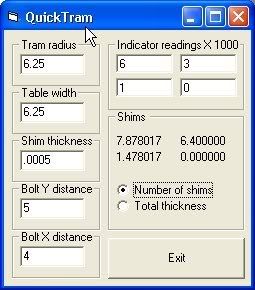
Again, I am using a complicated bit of kit. The only reason for this, it was the only thing I could reach in my storage shed, normally I would use a bit of right angle bent rod, 8" long with a DTI stuck on the end. There are now dedicated tramming tools on the market, but you can easily duplicate one with a couple of cheap clock gauges and a bit of ally plate.
So what you do is bring the DTI down onto the table until it registers, then zero the clock outer ring. Very carefully (running it gently over a sheet of thick paper, or as I do litho plate) swing thru 180 degrees to the other side of the table.

Just like this.
Then adjust the head to half the error.
Repeat this until when you swing from one side to the other, you get the same or very close reading. Tighten up and recheck it hasn't moved.

This is my finished setting, 0.00015" over about 9", that is close enough for me. If you need better than this, good luck.

So now we have a level table and a vertical head, the machine is nearly ready to cut, or is it?
This next bit is about one of the most abused items on a mill, but should be treated like a precision instrument.>>>>>>>>>>>>>>>>>>>>>>>>
-------------------------------------------------------------------------------------
THE VICE.
People just go out and buy any old vice, slap it down onto the table, grab a handful of bolts or clamps out of the scrap box and screw it down. Then they wonder why their machine doesn't cut to size and nothing ends up parallel.
Your vice should be the best quality you can afford and maybe some. It is the interface between machine and job and if it isn't set up correctly, you just might as well use duct tape to stick things onto the table.
First things first, get yourself the best vice you can.
The next thing is getting it fixed to the table. Chocolate and rubber nuts and bolts out of the scrap box just will not do, not only are they usually not up to the job, they can also cause damage to your machinery. Just wait until you see a table that has had its t-slot ripped out, because someone thought it would be cheaper and a good idea to use a hex headed bolt instead.
I had these given to me with the mill, and are dirt cheap nowadays.

But instead of breaking up a perfectly good set, I bought a few extra t-nuts, studs and clamp nuts

These were modified for a perfect fit to clamp my vice down to the table. I will modify some more for my RT and dividing head, as they all have different thickness bases.
So now we have some strong, high tensile steel fittings, the vice was bolted roughly in the middle of the table. Later on I will see if I can mount both vice and RT on the table, to save me having to swap them over.

Ignoring the C spanner, if you haven't got these other tools or something similar, go no further, if you do, read on.
The 3-2-1 block should really be a parallel, but I couldn't, as usual, get to them at this time (that will teach me to pack everything away).

The block was resting on the bottom of the vice but sticking up above the jaws. As I said I would normally use a parallel, only because it is my way, you could run the DTI across the fixed jaw instead.
The vice shouldn't be tight down, just nipped up at the moment.
With the DTI in the spindle, move the table until the DTI just touches the parallel plus a little bit, at one end as shown, zero the dial. Wind on the X axis to move the DTI across the face of the parallel.

Normally if the needle goes clockwise it means that the parallel is getting closer to you at the end the clock is on. Wind off the DTI and tap the end of the vice near where the handle fits on the right hand side, only tap it gently. The reason you take the clock away is that the sudden shock of tapping can destroy the very fine inner gearing.
Retouch on with the clock, re-zero and traverse to the other side. You keep tapping and traversing until you get fairly close (within a couple of thou), then tighten up the nuts, but not white knuckle tight just yet. Keep going until you either get it perfect or within a couple of tenths. Then do the white knuckle job on the nuts. Recheck again to make sure it has stayed in tolerance.
This squareness check should be done at the start of each new job. Just put a DTI in the chuck and run it across. It only takes a couple of minutes each time, but it does make sure you are cutting as square as possible each and every time.

Now this is the bit where everone trusts the vice maker, don't. My last vice had a 0.002" runout from side to side, and I thought I had bought quality.
Open up the vice jaws and set the DTI as I have done. Zero the dial.

Now moving the table on the X axis, traverse across the base of the vice jaws until you get to the other side. Note the deviation. If you are lucky, like me this time, you have a good vice, treasure it.
If you do get a deviation you will have to pack up the down end with shims to correct it. Or if you have or know someone who has the machinery to set up the datum on the jaws bottom face, you can have the base machined to correct the runout.
If you do a lot of wide work, it might pay you to do a check across Y axis as well.

That's it my friends.
Four and a half hours to compose.
If you notice any glaring spelling or grammar mistakes, put it down to old age. Any other noticeable ommissions or errors, let me know and I will put it right.
Bog 'Wacked Out' Standard
Some of this information might be irrelevant, because of the type of machine you have. But hopefully, it will give you an insight into what and how and why it is done.
It covers machine levelling, tramming in the head, and fitting and setting up a vice
I will be showing you some precision instruments that you might not possess. Don't worry, you might be able to borrow them from a friend or from where you work. As time passes you might invest in some yourself.
This is how I do it, others might have a different method, so they can add onto this post, to show how they do it, then you can choose which method to go with.
Why level a machine?
There are lots of reasons, but I will concentrate on the two main ones. A level machine should in theory have less wear and stresses put on its slideways, because it will not have to cope with twisted ways and climbing slopes. The second and most important to myself, it will show up deviations from the norm if I do a quick level check. I am in fact setting the machine up as its own datum.
There are a few other obvious ones, like not having coolant rushing down to one end and pouring over the edge, and in bad situations, tooling sliding off the table.
In industry they go to inordinate levels to produce a machine that is level, they will take off tables so they only level up on the slides, and the use of lasers has now taken levelling to finite limits, and the list can go on forever. But in our situation, I think levelling the table will be good enough.
This is a picture of my levelling tools, all purchased second hand, the latest was the silver coloured clinometer, that I bought off fleabay for a very reasonable price. All the tools here, put together, have cost me under £100, so they are available if you search enough.
If you haven't any of these, at least you now know what they look like, and you might be able to borrow or hire one.
Using a site level is as much use as a chocolate fire screen, they are just not accurate enough
This is what they look like out of boxes. The levels are self explanatory, the clinometer is like an adjustable level and is mostly used for setting things at angles, but can be used as a level as well.
Before I started, I took the opportunity, because I had a nice expanse of clean flat metal (it doesn't need to be level, only near enough), to calibrate both the normal levels. The 12" one was slightly out.
Levels like these are classed as precision instruments, and should be treated as such. If you can handle and position them without the bubble breaking up, you are handling them correctly.
What else is needed?
If you have bottomless pockets with lots of cash in them, you would go for shock absorbing levelling feet. Some of these can cost as much as I paid for my machine.
So I will go for something on the rough and ready side.
I am lucky in the fact that an old friend (now gone to a better place supposedly) used to get me laser offcuts of stainless sheet in all sorts of thicknesses, coupled to a few bits of shim steel I have, that should do it.
On no account use non ferrous materials as they have a tendency over time to compress, and so you will lose level. One thing to note about using ferrous materials. If you give the machine a hard knock, it will slide over steel as though it were ice. So until you get the machine 'stuck' down, be a bit careful when handling big stuff around it. I will be using the machine for a few weeks, checking the level every so often, then I will give a seal all round the base with hard silicone to 'stick' it to the floor and to stop crap and livestock from getting underneath it.
Seeing that I have my own small/large levels I set them up on the machine, as close to the centre of table operations as possible. On my setup, the levels will not be moved at all until the levelling is done and dusted. For using just one, I would mark the table with felt tip in the X and Y axis so the level can be positioned fairly accurately each time you have to move it.
I did this by myself, using a pry bar and some hard plywood, swapping and changing shims under each corner until I got the level spot on. It took me the best part of five hours, because I had to shim, get up, get down and change the shim pattern, get up etc etc. If there were two of us, maybe an hour. Remember, hopefully you only ever have to level the machine once in its, or your lifetime, so you may as well get it right first time.
X axis
Y axis
BTW, one full division out on these precision levels equates to, on the X axis 0.0015" drop over 3ft.
Once the levelling is done, only then can you move on >>>>>>>>>>
----------------------------------------------------------------------------------
Tramming the head, or getting the cutters to cut right and on the level.
If you have a head, or column that allows the head to be tilted over to do angle cutting, then you really need to 'tram' the head in.
If you are cutting all the time in the X axis then the problem will only show itself as a back or fwds overcut, and can be used to your advantage to produce a superior machined finish. But on the other hand, if you do cut in the Y axis, then it can cause problems, because if the tram is out, you will get a sloping face on your cuts (the cutter is tilted at an angle slightly).
On some of the much larger machines, they can tilt the head both ways, and so need tramming in both directions, I will only be doing the tramming on the X axis (normal machines).
If you have a machine like a mill/drill or one that cannot be tilted, you have to make do with what the manufacturers have given you, unless you take a course on precision shimming on the base of a column.
How do we do it?
What needs to be done is measure how far the head is out, and move it to a position where it is at a true right angle to the table. How you adjust it varies from machine to machine, so I won't go into that part, you will have to read your destructions. I will show you how to measure it, to allow you to get it upright.
Again, I am using a complicated bit of kit. The only reason for this, it was the only thing I could reach in my storage shed, normally I would use a bit of right angle bent rod, 8" long with a DTI stuck on the end. There are now dedicated tramming tools on the market, but you can easily duplicate one with a couple of cheap clock gauges and a bit of ally plate.
So what you do is bring the DTI down onto the table until it registers, then zero the clock outer ring. Very carefully (running it gently over a sheet of thick paper, or as I do litho plate) swing thru 180 degrees to the other side of the table.
Just like this.
Then adjust the head to half the error.
Repeat this until when you swing from one side to the other, you get the same or very close reading. Tighten up and recheck it hasn't moved.
This is my finished setting, 0.00015" over about 9", that is close enough for me. If you need better than this, good luck.
So now we have a level table and a vertical head, the machine is nearly ready to cut, or is it?
This next bit is about one of the most abused items on a mill, but should be treated like a precision instrument.>>>>>>>>>>>>>>>>>>>>>>>>
-------------------------------------------------------------------------------------
THE VICE.
People just go out and buy any old vice, slap it down onto the table, grab a handful of bolts or clamps out of the scrap box and screw it down. Then they wonder why their machine doesn't cut to size and nothing ends up parallel.
Your vice should be the best quality you can afford and maybe some. It is the interface between machine and job and if it isn't set up correctly, you just might as well use duct tape to stick things onto the table.
First things first, get yourself the best vice you can.
The next thing is getting it fixed to the table. Chocolate and rubber nuts and bolts out of the scrap box just will not do, not only are they usually not up to the job, they can also cause damage to your machinery. Just wait until you see a table that has had its t-slot ripped out, because someone thought it would be cheaper and a good idea to use a hex headed bolt instead.
I had these given to me with the mill, and are dirt cheap nowadays.
But instead of breaking up a perfectly good set, I bought a few extra t-nuts, studs and clamp nuts
These were modified for a perfect fit to clamp my vice down to the table. I will modify some more for my RT and dividing head, as they all have different thickness bases.
So now we have some strong, high tensile steel fittings, the vice was bolted roughly in the middle of the table. Later on I will see if I can mount both vice and RT on the table, to save me having to swap them over.
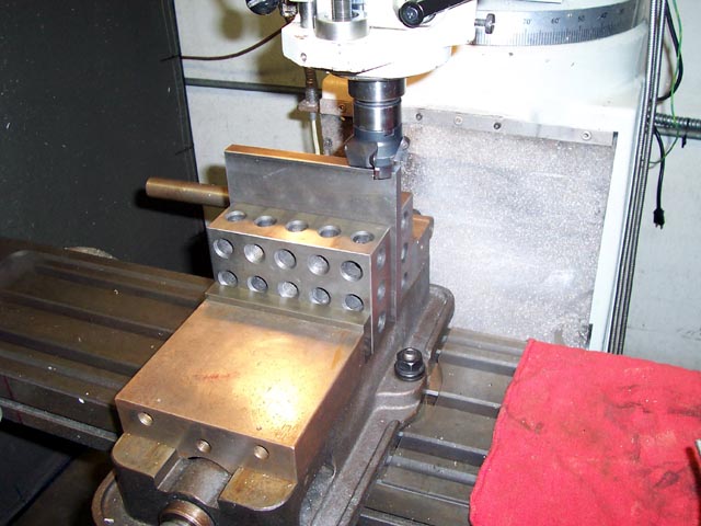
Ignoring the C spanner, if you haven't got these other tools or something similar, go no further, if you do, read on.
The 3-2-1 block should really be a parallel, but I couldn't, as usual, get to them at this time (that will teach me to pack everything away).
The block was resting on the bottom of the vice but sticking up above the jaws. As I said I would normally use a parallel, only because it is my way, you could run the DTI across the fixed jaw instead.
The vice shouldn't be tight down, just nipped up at the moment.
With the DTI in the spindle, move the table until the DTI just touches the parallel plus a little bit, at one end as shown, zero the dial. Wind on the X axis to move the DTI across the face of the parallel.
Normally if the needle goes clockwise it means that the parallel is getting closer to you at the end the clock is on. Wind off the DTI and tap the end of the vice near where the handle fits on the right hand side, only tap it gently. The reason you take the clock away is that the sudden shock of tapping can destroy the very fine inner gearing.
Retouch on with the clock, re-zero and traverse to the other side. You keep tapping and traversing until you get fairly close (within a couple of thou), then tighten up the nuts, but not white knuckle tight just yet. Keep going until you either get it perfect or within a couple of tenths. Then do the white knuckle job on the nuts. Recheck again to make sure it has stayed in tolerance.
This squareness check should be done at the start of each new job. Just put a DTI in the chuck and run it across. It only takes a couple of minutes each time, but it does make sure you are cutting as square as possible each and every time.
Now this is the bit where everone trusts the vice maker, don't. My last vice had a 0.002" runout from side to side, and I thought I had bought quality.
Open up the vice jaws and set the DTI as I have done. Zero the dial.
Now moving the table on the X axis, traverse across the base of the vice jaws until you get to the other side. Note the deviation. If you are lucky, like me this time, you have a good vice, treasure it.
If you do get a deviation you will have to pack up the down end with shims to correct it. Or if you have or know someone who has the machinery to set up the datum on the jaws bottom face, you can have the base machined to correct the runout.
If you do a lot of wide work, it might pay you to do a check across Y axis as well.
That's it my friends.
Four and a half hours to compose.
If you notice any glaring spelling or grammar mistakes, put it down to old age. Any other noticeable ommissions or errors, let me know and I will put it right.
Bog 'Wacked Out' Standard

")