Tin Falcon
Well-Known Member
- Joined
- Jul 9, 2007
- Messages
- 7,207
- Reaction score
- 787
Well guys I am starting this off as a break away from an earlier thread.
Dec 31 08
Well guys things are moving forward.
Last weekend I went to a computer show and purchased a used computer and monitor to run Mach 3.
Mach 3 has been downloaded I have printed the manuals and have been reading studying them and playing with the program some.
Today we ordered a g540 drive and some new motors from HOMESHOPCNC that are not up on the site yet they are 300 OZ motors wound to match the G540/G20/g251 family.
Thanks for all the help
looks like I am getting newly released stuff hope that is a good thing.
Jan 24 2009
Well am moving forward seems slow.
Lets see progress
Mach 3 seminar @Cabin Fever.
Motors and controllers in hand
Keling power supply in hand
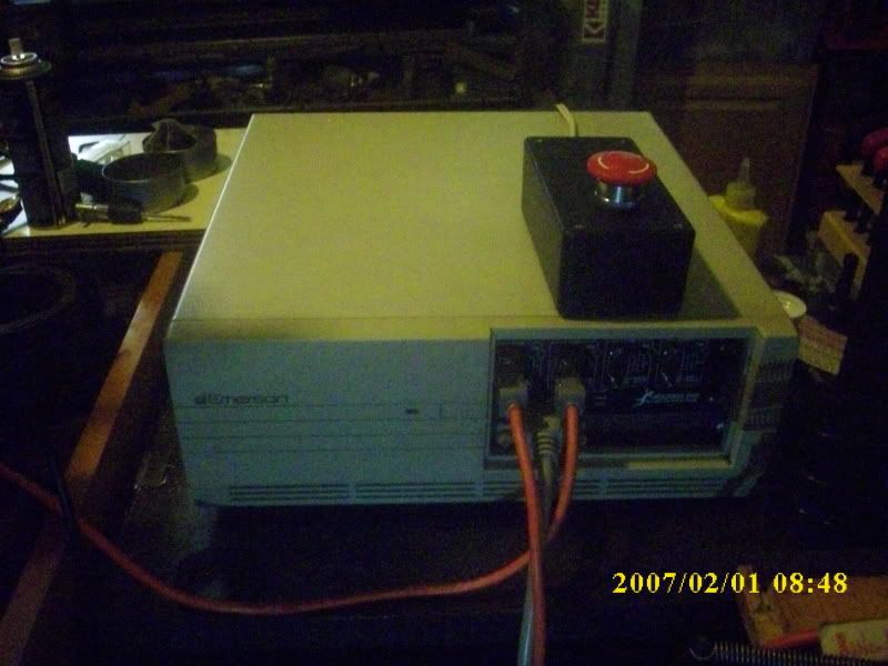
gutted old pc (XT ) for the box
Gutted the XT power supply to use the power connection switch and fan.
Last evening was a wash did not get home from work til 9pm.
Made adapter plate to mount G540 where drives used to go
mounted keling power supply
Went to radio shack today to get connector strips, fork connectors, resistors, a fuse holder, project box for the e-stop etc.
Cut and mounted a piece of marine starboard plastic so the fan power supply and the terminal blocks can be mounted also the spindle ps can be mounted later.
The apprentice is helping
Jan 25 09
I realized I need some more wire etc to build this to my liking and rely want to push forward. So decided to do a temp wire up to get things going. For now am just concentrating on getting the x-y axis going with the factory lead screws. will probaly order the ball screws in the next week or two.
Not sure if I am being lazy or wise but plan on getting the cnc going to finish the main Z axis mounting plate.
so today's progress:
power supply wired
gecko wired
e-stop box drilled e-stop button wired
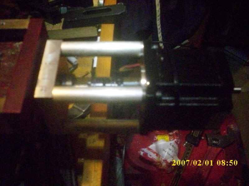
x-axis motor wired
I kept the face plate of the old XT power supply so plan on using the input power plug the switch and the fan but will hook them up later. I am glad I have had to solder up a few DB9 connectors at work in the past few months the practice has come in handy.
1 Feb 09
Well during the week powered up the gecko only to find the fault light came on and would not clear. After about 2 hours of frustrated head scratching found that gecko has revised the manual and posted a start up guide. I had to reset the computer bios to get the charge pump to work also found we had attached the wires for the e-stop to the NO side instead of the NC.
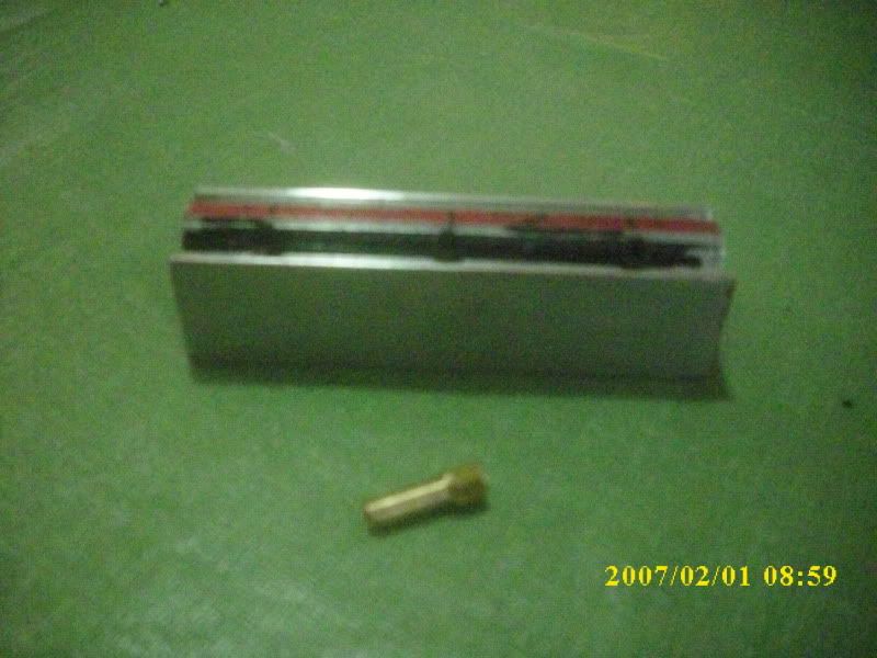
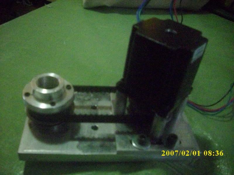
The memory of the computer has been upgraded to the needed 512 mb. The motors are hooked up and running. I am having trouble with the Stirling Steele design couplings so will have to buy or make some Olham couplings or buy some lovejoy couplings. If the cnc was operational they would be easy to make.LOL
Tin
I know need to get some pics up.
Dec 31 08
Well guys things are moving forward.
Last weekend I went to a computer show and purchased a used computer and monitor to run Mach 3.
Mach 3 has been downloaded I have printed the manuals and have been reading studying them and playing with the program some.
Today we ordered a g540 drive and some new motors from HOMESHOPCNC that are not up on the site yet they are 300 OZ motors wound to match the G540/G20/g251 family.
Thanks for all the help
looks like I am getting newly released stuff hope that is a good thing.
Jan 24 2009
Well am moving forward seems slow.
Lets see progress
Mach 3 seminar @Cabin Fever.
Motors and controllers in hand
Keling power supply in hand
gutted old pc (XT ) for the box
Gutted the XT power supply to use the power connection switch and fan.
Last evening was a wash did not get home from work til 9pm.
Made adapter plate to mount G540 where drives used to go
mounted keling power supply
Went to radio shack today to get connector strips, fork connectors, resistors, a fuse holder, project box for the e-stop etc.
Cut and mounted a piece of marine starboard plastic so the fan power supply and the terminal blocks can be mounted also the spindle ps can be mounted later.
The apprentice is helping
Jan 25 09
I realized I need some more wire etc to build this to my liking and rely want to push forward. So decided to do a temp wire up to get things going. For now am just concentrating on getting the x-y axis going with the factory lead screws. will probaly order the ball screws in the next week or two.
Not sure if I am being lazy or wise but plan on getting the cnc going to finish the main Z axis mounting plate.
so today's progress:
power supply wired
gecko wired
e-stop box drilled e-stop button wired
x-axis motor wired
I kept the face plate of the old XT power supply so plan on using the input power plug the switch and the fan but will hook them up later. I am glad I have had to solder up a few DB9 connectors at work in the past few months the practice has come in handy.
1 Feb 09
Well during the week powered up the gecko only to find the fault light came on and would not clear. After about 2 hours of frustrated head scratching found that gecko has revised the manual and posted a start up guide. I had to reset the computer bios to get the charge pump to work also found we had attached the wires for the e-stop to the NO side instead of the NC.
The memory of the computer has been upgraded to the needed 512 mb. The motors are hooked up and running. I am having trouble with the Stirling Steele design couplings so will have to buy or make some Olham couplings or buy some lovejoy couplings. If the cnc was operational they would be easy to make.LOL
Tin
I know need to get some pics up.