


You may ask, why do I need a resettable zero point?
When you buy an imperial lathe, the screwcutting dial just has one gear on the bottom, and the zero mark is usually set up at the factory by use of shims on the holder. So in use, the marks drop in the correct position and everything is in sync with the leadscrew.
With a metric machine, you change gears for each pitch range of threads you cut. So normally, you would put the correct gear on the bottom of the dial, and play about with the gear position to realign the zero mark. By doing this mod, no matter where the gear is on the shaft, a few seconds and I can realine the zero drop in point. Also I have locked all three gears onto my shaft, so gear realignment isn't possible. This also has a direct relationship to that post about the drop in gauge, where I mounted all three gears at the same time.
Starting out with a ruler and a bit of stainless sheet, I did a quickie sketch up of what was required.
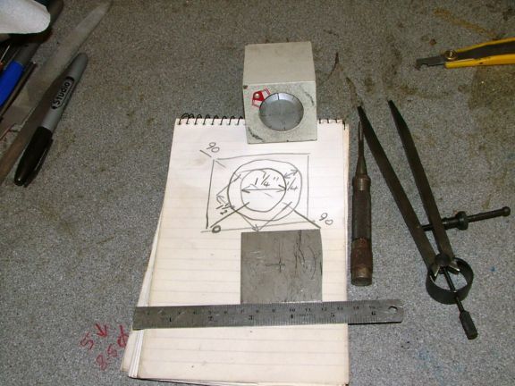
The sketch was transferred onto the blued up plate. I could have gone the hard way, and cut and filed it all up by hand. But I have the facilities to take all the hard work out of it, so decided to go down that road. Anything for an easy life.
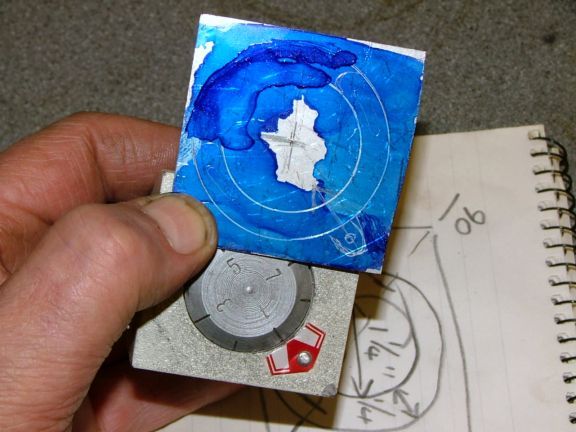
So what follows is a rough and ready bit of machining, no precision measuring, just cutting to lines with a 'that will do' attitude.
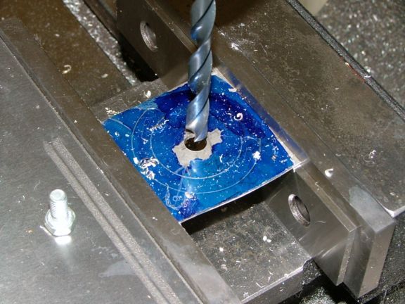
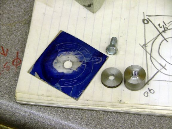
So an 8mm hole was wacked thru the plate at the pop marked position.
Using rough and ready materials, I made up a mandrel to fit the plate onto.
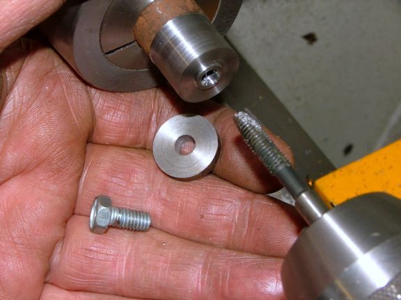
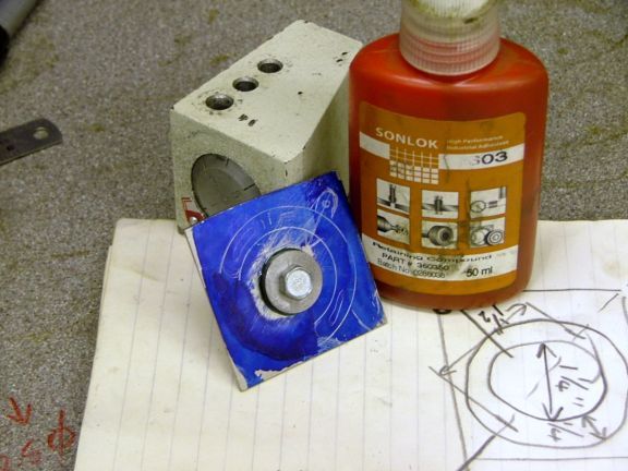
If you notice, even the bolt is a low tensile throw away job from the bitsa box. This mandrel will be thrown away after it is finished with.
This will be a plunge thru and cut away job, so I want nothing coming loose. The whole lot was assembled with loctite.
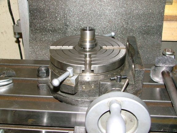
This was the only precision bit on the job. The RT was zeroed up in X&Y and also the scale was zeroed.
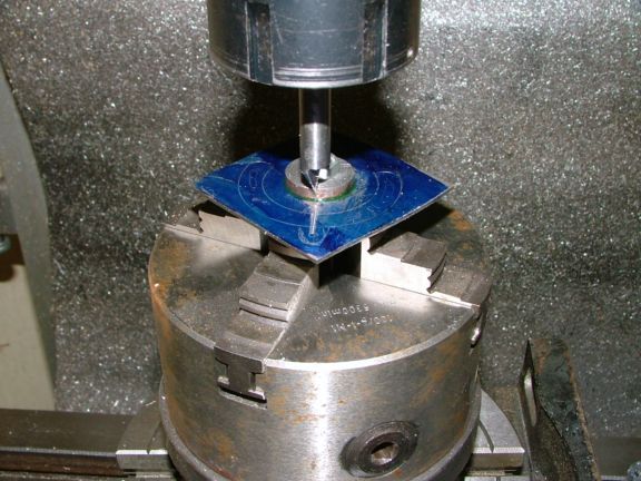
An engraving bit was mounted into the collet, and the plate rotated in the chuck so that when I moved it in the Y axis, it followed the line and ended up at the small hole marking I had put at the outside. The chuck was then fully tightened with the mandrel standing proud enough, that when I would be cutting, the cutter wouldn't hit the chuck jaws.
A line was then engraved from the edge of the mandrel to the small hole position. After that, a centre drill was spotted thru at the hole position.
Turn the RT thru 90 degs, and wind the table in the X until the drill was about midway between the two outer lines, the central hole was then drilled and another hole at either side at 10 degrees offset either way from the first hole. RT rotated to 270 degs and the same thing again.
A 3mm slot drill was plunged thru in the same position as the holes that had been drilled (180, 270) and the RT fed 10 degs either way. This operation made the two curved slots that are required.
A larger cutter was fitted and the job moved in the X axis until it was off the plate. The cutter was fed to depth, and brought in from the side until it met the edge of the outside circle. The RT was then rotated either way until the outside was cleaned up to where I wanted it. The tool was then plunged in and the inner cut done. This needed to be started and finished at a point close together, to provide maximum support of the ring being cut out until the very final bit. Maybe I should have done that on the back, but my original idea was to have a pointer sticking out, it was later that I decided I didn't like the look.
You can just see the plunge and extraction point for the cutter, either side of the engraved line.
The part was snipped away from the mandrel, and the mandrel was thrown away, it has no further use.
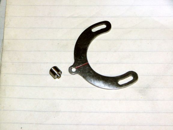
After the original zero mark was removed and the part given a rough trimming, it was tried for size. That will do me.
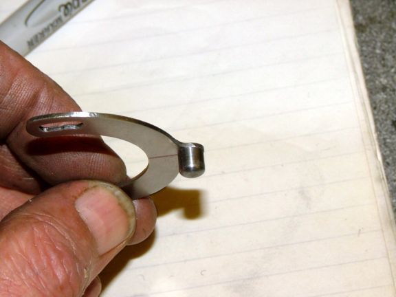
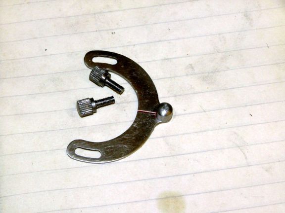
This is after a bit of filing and dressing up. I also made a thumb push knob from a bit of 6mm SS rod. The small hole was drilled thru and a countersink put on the back.
A couple of wacks with a big hammer had the knob rivetted in position.
I now needed a couple of finger screws, so a bit more 6mm rod, a little turning and knurling had them ready to be threaded. That was done with a 3mm die.
BTW straight knurls for tightening & undoing, diamond pattern for gripping.
Finished bits ready for fitting.
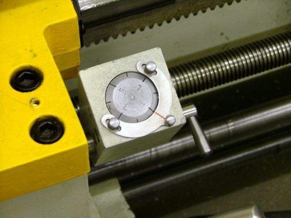
After drilling and tapping a couple of holes, here is the finished article on the machine.
It works a treat with all three gears. Taking only seconds to realign the zero position.
Before anyone asks, the chuck on my RT is a self centring four jaw, NOT independent.
I hope you have enjoyed my little foray into non precision machining. At times, things can be done this way, and it makes a nice change from number crunching
Job done
John
When you buy an imperial lathe, the screwcutting dial just has one gear on the bottom, and the zero mark is usually set up at the factory by use of shims on the holder. So in use, the marks drop in the correct position and everything is in sync with the leadscrew.
With a metric machine, you change gears for each pitch range of threads you cut. So normally, you would put the correct gear on the bottom of the dial, and play about with the gear position to realign the zero mark. By doing this mod, no matter where the gear is on the shaft, a few seconds and I can realine the zero drop in point. Also I have locked all three gears onto my shaft, so gear realignment isn't possible. This also has a direct relationship to that post about the drop in gauge, where I mounted all three gears at the same time.
Starting out with a ruler and a bit of stainless sheet, I did a quickie sketch up of what was required.
The sketch was transferred onto the blued up plate. I could have gone the hard way, and cut and filed it all up by hand. But I have the facilities to take all the hard work out of it, so decided to go down that road. Anything for an easy life.
So what follows is a rough and ready bit of machining, no precision measuring, just cutting to lines with a 'that will do' attitude.
So an 8mm hole was wacked thru the plate at the pop marked position.
Using rough and ready materials, I made up a mandrel to fit the plate onto.
If you notice, even the bolt is a low tensile throw away job from the bitsa box. This mandrel will be thrown away after it is finished with.
This will be a plunge thru and cut away job, so I want nothing coming loose. The whole lot was assembled with loctite.
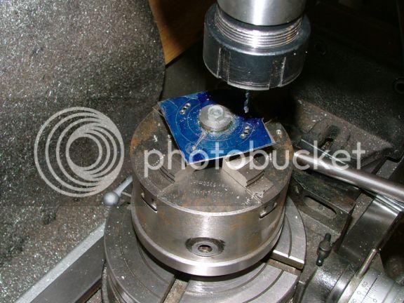
This was the only precision bit on the job. The RT was zeroed up in X&Y and also the scale was zeroed.
An engraving bit was mounted into the collet, and the plate rotated in the chuck so that when I moved it in the Y axis, it followed the line and ended up at the small hole marking I had put at the outside. The chuck was then fully tightened with the mandrel standing proud enough, that when I would be cutting, the cutter wouldn't hit the chuck jaws.
A line was then engraved from the edge of the mandrel to the small hole position. After that, a centre drill was spotted thru at the hole position.
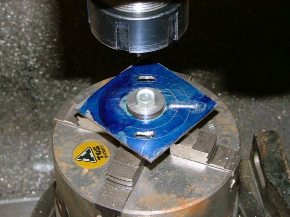
Turn the RT thru 90 degs, and wind the table in the X until the drill was about midway between the two outer lines, the central hole was then drilled and another hole at either side at 10 degrees offset either way from the first hole. RT rotated to 270 degs and the same thing again.
A 3mm slot drill was plunged thru in the same position as the holes that had been drilled (180, 270) and the RT fed 10 degs either way. This operation made the two curved slots that are required.
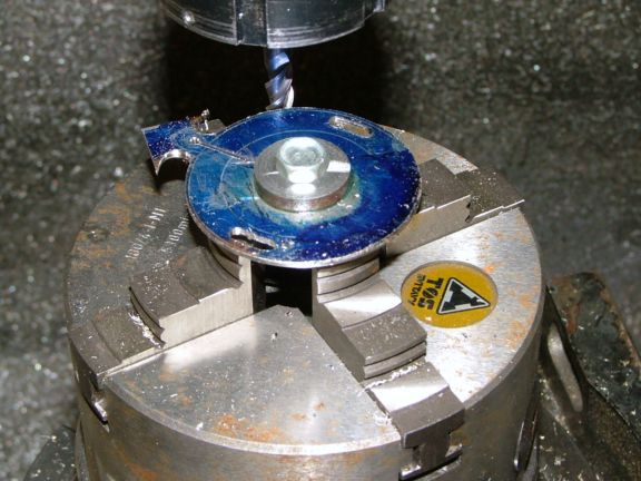
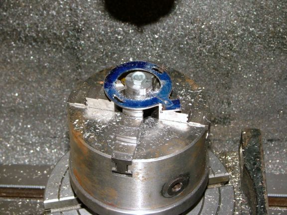
A larger cutter was fitted and the job moved in the X axis until it was off the plate. The cutter was fed to depth, and brought in from the side until it met the edge of the outside circle. The RT was then rotated either way until the outside was cleaned up to where I wanted it. The tool was then plunged in and the inner cut done. This needed to be started and finished at a point close together, to provide maximum support of the ring being cut out until the very final bit. Maybe I should have done that on the back, but my original idea was to have a pointer sticking out, it was later that I decided I didn't like the look.
You can just see the plunge and extraction point for the cutter, either side of the engraved line.
The part was snipped away from the mandrel, and the mandrel was thrown away, it has no further use.
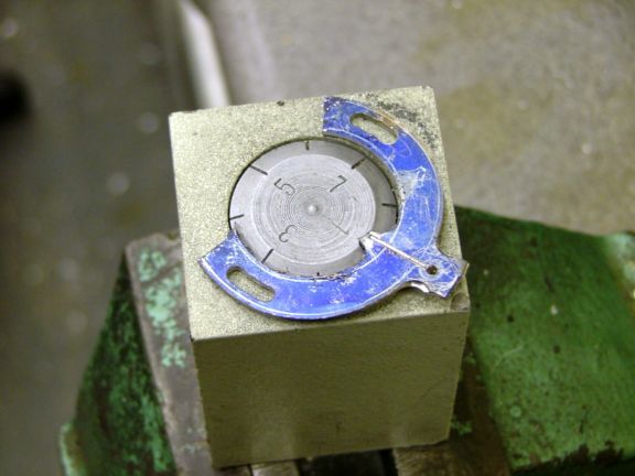
After the original zero mark was removed and the part given a rough trimming, it was tried for size. That will do me.
This is after a bit of filing and dressing up. I also made a thumb push knob from a bit of 6mm SS rod. The small hole was drilled thru and a countersink put on the back.
A couple of wacks with a big hammer had the knob rivetted in position.
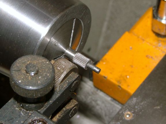
I now needed a couple of finger screws, so a bit more 6mm rod, a little turning and knurling had them ready to be threaded. That was done with a 3mm die.
BTW straight knurls for tightening & undoing, diamond pattern for gripping.
Finished bits ready for fitting.
After drilling and tapping a couple of holes, here is the finished article on the machine.
It works a treat with all three gears. Taking only seconds to realign the zero position.
Before anyone asks, the chuck on my RT is a self centring four jaw, NOT independent.
I hope you have enjoyed my little foray into non precision machining. At times, things can be done this way, and it makes a nice change from number crunching
Job done
John
")