Well, its been a couple months since completing the Elmers #6 so I guess its time for another project. I had been considering Elmers mine engine since before completing #6, but all the Stirling projects going on stirred up some old burning embers.
Ive been deeply interested in Stirlings since I first started reading about them in Popular Science and Popular Mechanics as a youngster in the early 70s. The Stirling was going to change the world, they said. We all know how that turned out; still, its a very interesting engine.
The magazine articles never went into the history of the engine, just talking up all the revolutionary research and development that was going on made it sound like it was some new engineering principle that had escaped from the darkest corners of Caltech or MIT. I was quite surprised years later to find out that it predates the Otto and Diesel cycle engines.
My first foray into the world of Stirling was about 20 years ago when I made a tin can model I had found plans for while surfing the pre-internet (library!). It was a wooden framed affair with a couple coffee cans for cylinders and soup cans for pistons with water to seal them. It was an Alpha type with one can being hot and the other cold, a fabricated copper pipe plumbed them together. I never did get it to work right; I think I got at most 2 revolutions before it would stop.
Now I venture into the world of Stirlings again, not armed with some plans from a faded magazine of days gone by. No, not this time. This time its scratch built. My own design. I dont have any plans or drawing made, just some numbers scratched out on a pad and the worst (incomplete) C-o-C youve ever seen. It makes a 7 year olds stick figure Hangmans drawing look like it was done by da Vinci.
Its time to give credit where credit is due. There is nothing new under the Sun. Im relying on lots of people who have gone before me. In that vein Ive borrowed heavily from the designs of Terry Coss. His designs are straight forward and to the point yet quite elegant in motion and function in a modernistic style. Fear not, Cedge, your Victorian art is quite safe.
Now, on with the show
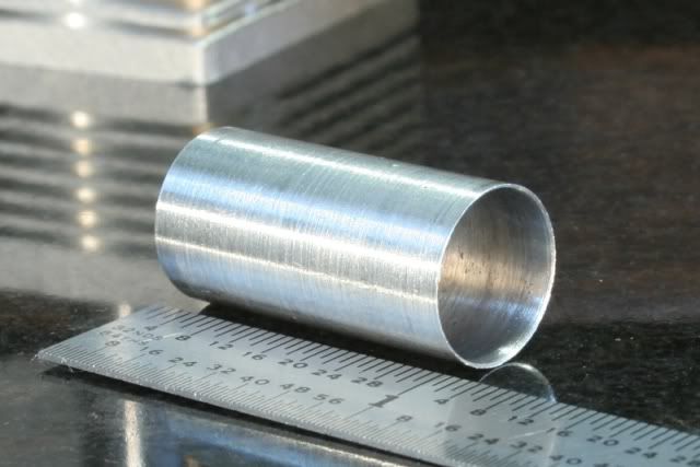
I started with the hot cap using the classic rule of 3. The displacer cylinder is 3 times the diameter, the displacer piston length is 2/3 the length of the cylinder. The swept volume of the power cylinder is equal to the swept volume of the displacer, 1/3 the volume of the displacer cylinder. Everybody got that? Theres a test afterward.
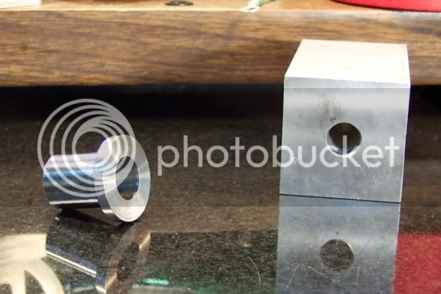
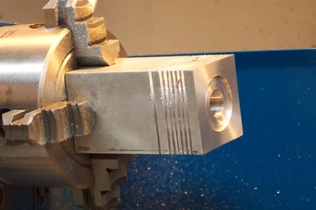
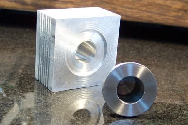
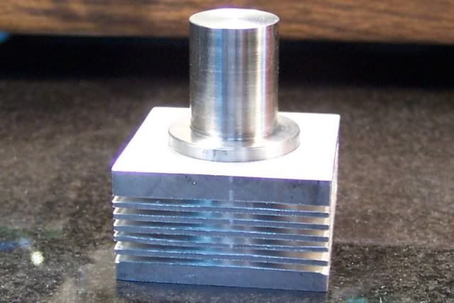
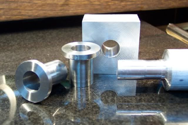
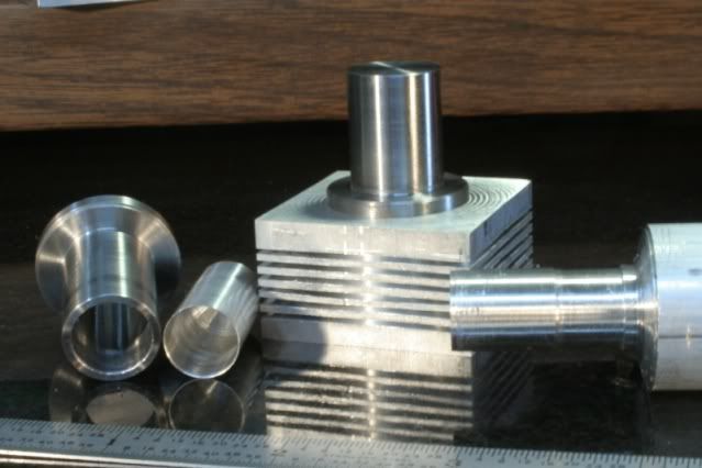
The cylinder inside diameter is 1/2 inch, as thats the largest reamer I have. The hot cap is 12L14 steel, as thats what I had on hand, with a length (inside) of 3/4 inch, 1/2 the cylinder length. The cold side will also be 3/4 inch long. I have several of those aluminum blocks with the hole already drilled in them, now I know what to do with them. The hole is .400 inches, the block is about 1.5 inches on a side and 3 inches long, give or take.
It was a little warm in the shop so thats as far as I got.
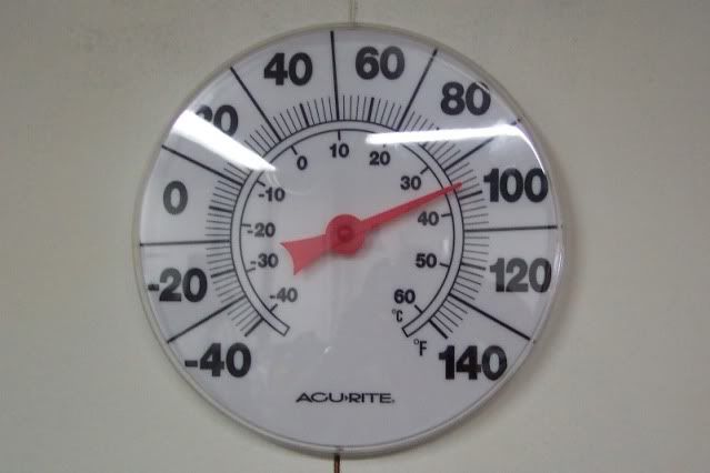
Im not fond of sweat dripping off my nose and onto the machinery and glasses. The air conditioning wont arrive until October, so this is likely to be a very slow build.
Thanks for stopping in. I hope the next installment isnt too far away.
Ive been deeply interested in Stirlings since I first started reading about them in Popular Science and Popular Mechanics as a youngster in the early 70s. The Stirling was going to change the world, they said. We all know how that turned out; still, its a very interesting engine.
The magazine articles never went into the history of the engine, just talking up all the revolutionary research and development that was going on made it sound like it was some new engineering principle that had escaped from the darkest corners of Caltech or MIT. I was quite surprised years later to find out that it predates the Otto and Diesel cycle engines.
My first foray into the world of Stirling was about 20 years ago when I made a tin can model I had found plans for while surfing the pre-internet (library!). It was a wooden framed affair with a couple coffee cans for cylinders and soup cans for pistons with water to seal them. It was an Alpha type with one can being hot and the other cold, a fabricated copper pipe plumbed them together. I never did get it to work right; I think I got at most 2 revolutions before it would stop.
Now I venture into the world of Stirlings again, not armed with some plans from a faded magazine of days gone by. No, not this time. This time its scratch built. My own design. I dont have any plans or drawing made, just some numbers scratched out on a pad and the worst (incomplete) C-o-C youve ever seen. It makes a 7 year olds stick figure Hangmans drawing look like it was done by da Vinci.
Its time to give credit where credit is due. There is nothing new under the Sun. Im relying on lots of people who have gone before me. In that vein Ive borrowed heavily from the designs of Terry Coss. His designs are straight forward and to the point yet quite elegant in motion and function in a modernistic style. Fear not, Cedge, your Victorian art is quite safe.
Now, on with the show
I started with the hot cap using the classic rule of 3. The displacer cylinder is 3 times the diameter, the displacer piston length is 2/3 the length of the cylinder. The swept volume of the power cylinder is equal to the swept volume of the displacer, 1/3 the volume of the displacer cylinder. Everybody got that? Theres a test afterward.
The cylinder inside diameter is 1/2 inch, as thats the largest reamer I have. The hot cap is 12L14 steel, as thats what I had on hand, with a length (inside) of 3/4 inch, 1/2 the cylinder length. The cold side will also be 3/4 inch long. I have several of those aluminum blocks with the hole already drilled in them, now I know what to do with them. The hole is .400 inches, the block is about 1.5 inches on a side and 3 inches long, give or take.
It was a little warm in the shop so thats as far as I got.
Im not fond of sweat dripping off my nose and onto the machinery and glasses. The air conditioning wont arrive until October, so this is likely to be a very slow build.
Thanks for stopping in. I hope the next installment isnt too far away.
")