SAM's Rendition of Elmers #2 Twin Wobbler

Home Model Engine Machinist Forum

Help Support Home Model Engine Machinist Forum:

This site may earn a commission from merchant affiliate links, including eBay, Amazon, and others.

SAM in LA

Well-Known Member
Joined
Oct 20, 2009
Messages
746
Reaction score
8
Here is the video of my second build, Elmer Verburg's #2 Vertical Twin Wobbler, Warts and All.

[ame]http://www.youtube.com/watch?v=xmdBywJy7fE[/ame]

Photos and narrative will follow shortly after the Bling Spirits make a house call.

It is only because of the great builds that have been posted on this forum, that I was able to machine this engine.

Thanks to all,

:bow:

SAM

 
Would someone please explain to me why the YouTube link shows up twice when I paste the "embed" code.

Thanks

SAM
 
It was a change in the software.
You don't need to use the embed thing any longer.
Just copy and paste the URL, no tags are required, such as:

Code:
http://www.youtube.com/v/xmdBywJy7fE&hl=en_US&fs=1&

Will result in:

http://www.youtube.com/v/xmdBywJy7fE&hl=en_US&fs=1&

Nice Runner! Thm:

Rick
 
Congrats on your second successful build! :bow:

Engine #2, Elmer's #2. How appropriate!

I sounds like its running really fast. That's good!

I like the #2, is a great high speed running low vibration design.

Give us a few still shots, after the bling fairy pays you a visit. :big:

-MB
 
It really goes, Sam. Congrats on another successful build!

re: Bling. I find if you put a piece of chilled cast iron under your pillow, that annoying bling fairy will stop bothering you.

Dean
 
Nicely done Sam. I've done a #2 as my second as well. No video yet, but a couple of stills. You'll instantly notice my modification of the porting so as to bring the input through the same face as the exhaust.

I've not run it nearly as fast as your video, but it does chuff along nicely at about 3PSI.

The background happens to to be one of Rudy Kouhoupt's Shop Wisdom volumes

Thayer

EE2_V-twin_13384cw.jpg


EE2_V-twin_13385cw.jpg
 
thayer said:
Nicely done Sam. I've done a #2 as my second as well. You'll instantly notice my modification of the porting so as to bring the input through the same face as the exhaust.

I've not run it nearly as fast as your video, but it does chuff along nicely at about 3PSI.

Thayer

Thayer

Thanks. I need to get some 1/8" drill rod to use for the both of the shafts. I used some mild steel rod I found at Home Depot. It is not the straightest stuff. I also need to reduce the spring pressure on the pivot shafts. After that, it should be able to run on "clear steam"at a much lower pressure. SAM
 
Metal Butcher said:
Congrats on your second successful build! :bow:

Engine #2, Elmer's #2. How appropriate!

I sounds like its running really fast. That's good!

I like the #2, is a great high speed running low vibration design.

Give us a few still shots, after the bling fairy pays you a visit. :big:

-MB

MB,
Thanks. I'm curious to how fast it really runs.
SAM

Deanofid said:
It really goes, Sam. Congrats on another successful build!

re: Bling. I find if you put a piece of chilled cast iron under your pillow, that annoying bling fairy will stop bothering you.

Dean

Thanks Dean. Would a chilled Glock work?

substandard said:
Looks good :bow:

SS,

Thanks.
SAM


SAM in LA said:
Thayer

Thanks. I need to get some 1/8" drill rod to use for the both of the shafts.

Sam, do you have any larger drill rod? I discovered in the middle of the night that I didn't have any 1/8-inch either. Ended up turning down some 3/16 or 1/4 held in a collet. Slid it out a bit at a time and it worked out well.

Thayer
 
I was kind of jealous when some peoples work could be considered a work of Art.

So, does this qualify as Art?

TwinWobbler032610025.jpg


Rof}

SAM
 
SAM in LA said:
I was kind of jealous when some peoples work could be considered a work of Art.

So, does this qualify as Art?

Rof}

SAM

Move over Van Gogh ::)
 
SAM in LA said:
Thanks Dean. Would a chilled Glock work?

SS,

No, but a 1911 should do it. You shouldn't need more than eight shots for one little fairy, you know.

Dean
 
SAM’s rendition of Elmer Verburg’s #2 Vertical Twin Wobbler.
This is my second build using a loose 1994 Shop Task 3 in 1 machine. I keep learning more about the capabilities and limitations of this old machine. The plans I used are available free at http://www.john-tom.com/ElmersEngines/02_twinVwobbler.pdf .
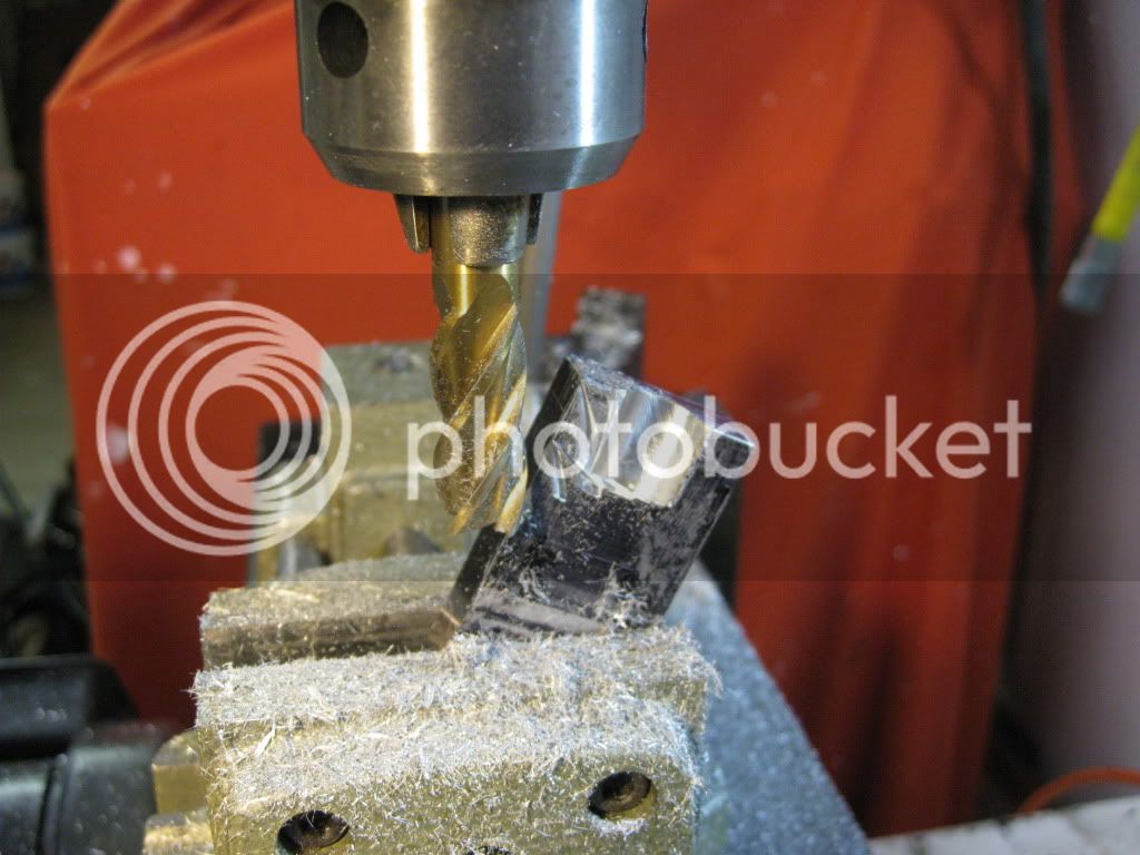
I started out by rough cutting the base, column and cylinders from some scrap aluminum, type unknownium. I learned how not to mill the column, as you can see.

TwinWobbler032610001.jpg


I was being a bit to aggressive and the cutter quit cutting and the material would not submit. Sure makes the adrenalin kick in. Perhaps there is a better way to set this up. Time to try again.


TwinWobbler032610011.jpg


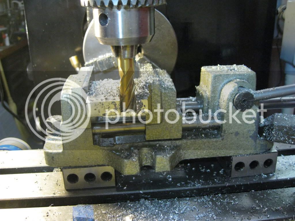
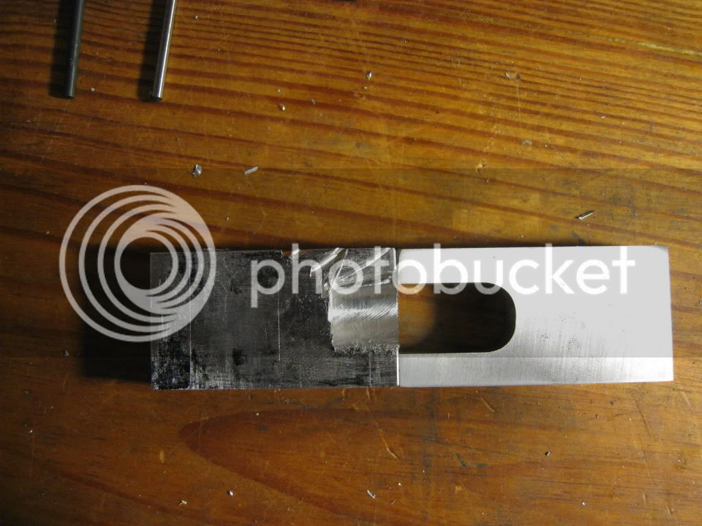
It was much easier to cut the slot when the material is lying down. I continued by milling to the correct width after the slot was cut.

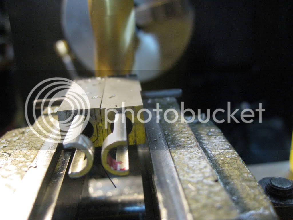
I continued and squared up and milled to size the base and 2 cylinders, which are rectangular.
TwinWobbler032610006-1.jpg

TwinWobbler032610024.jpg


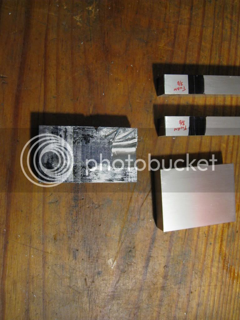
You may notice that the first column I tried to mill in the vertical position is shorter than my second attempt. I was going to make the engine shorter to fit the material I had which would not require an additional cut. By trying to save time, I ended up having to do it twice.
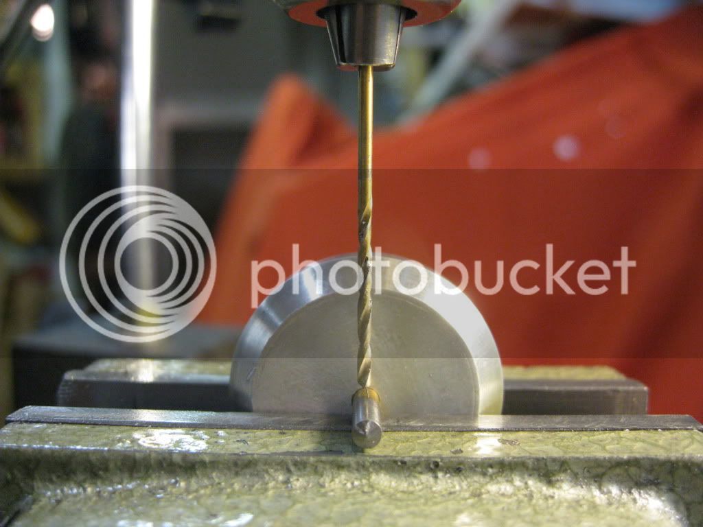
Next I peck drilled and reamed the horizontal holes in the column for the crankshaft and pivot shaft. I used lots of oil.

TwinWobbler032610026.jpg


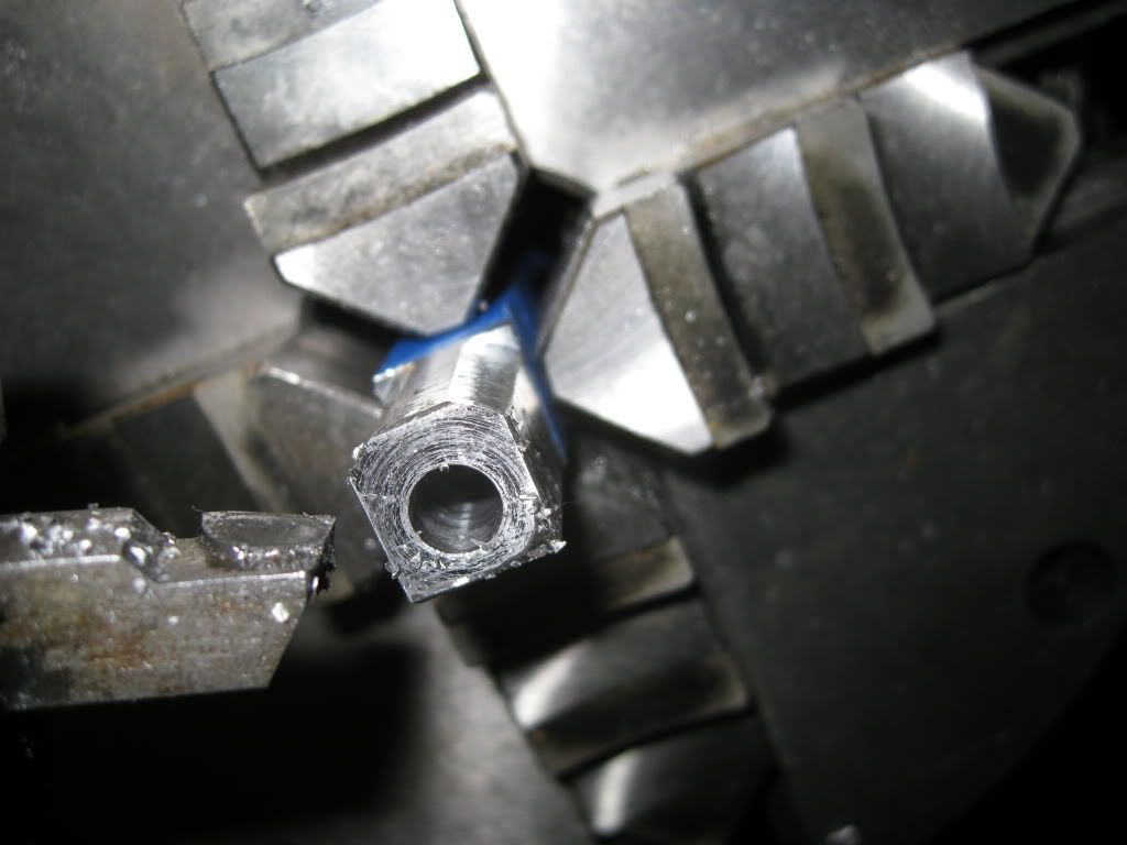
I then set up my 4 jaw chuck so I could drill/ream the 0.250 “ the cylinder holes and turn the piston guide, which is similar to a cross-head guide. This was interesting to set up for the cut since the hole is offset and the parts cylinder cross-section is not exactly square.
TwinWobbler032610030.jpg


TwinWobbler032610035.jpg


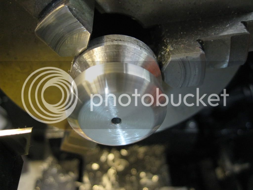
I turned the flywheel out of some 6061 I had. I did not machine the sheave per the drawing and I beveled the sides. I think that the flywheel looks better this way when it is mounted in the column. It’s ready to be parted off.

TwinWobbler032610037.jpg


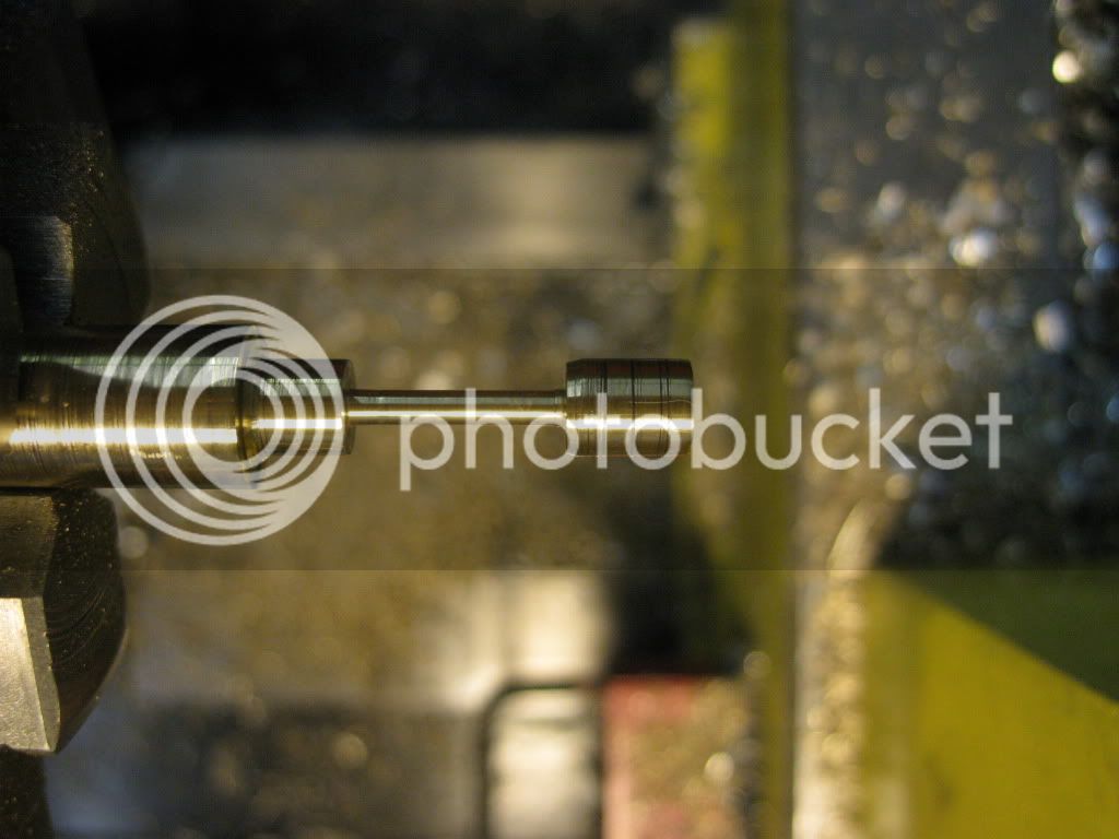
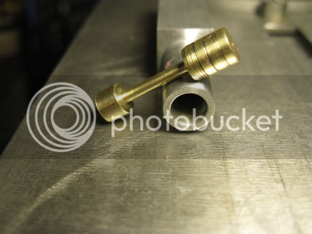
Next up is to machine the 2 pistons out of brass. I turned the pistons OD to fit the cylinder bore. Then I machine the rod portion working from the right to the left. The crank end boss was then turned to its finished OD and parted off. By turning the each portion of the piston from right to left maximized the rigidity. I found that by using the parting tool at the finished depth, I was able to take a full cut from right to left. The piston/cylinder are match marked pairs.
TwinWobbler032610041.jpg


TwinWobbler032610050.jpg


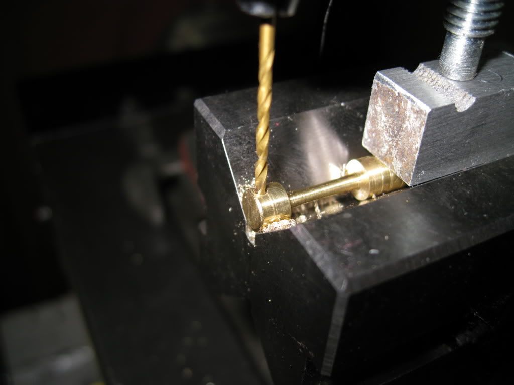
The crank end of the piston assembly requires a 1/16” hole to be drilled through and parallel flats milled.
TwinWobbler032610062.jpg


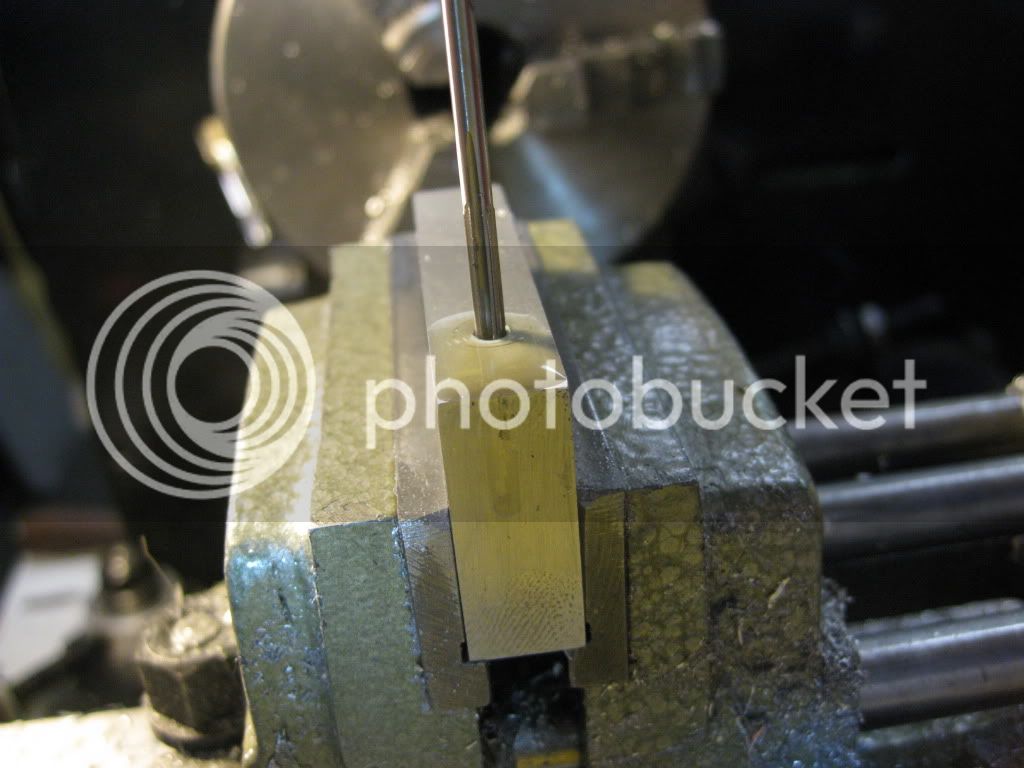
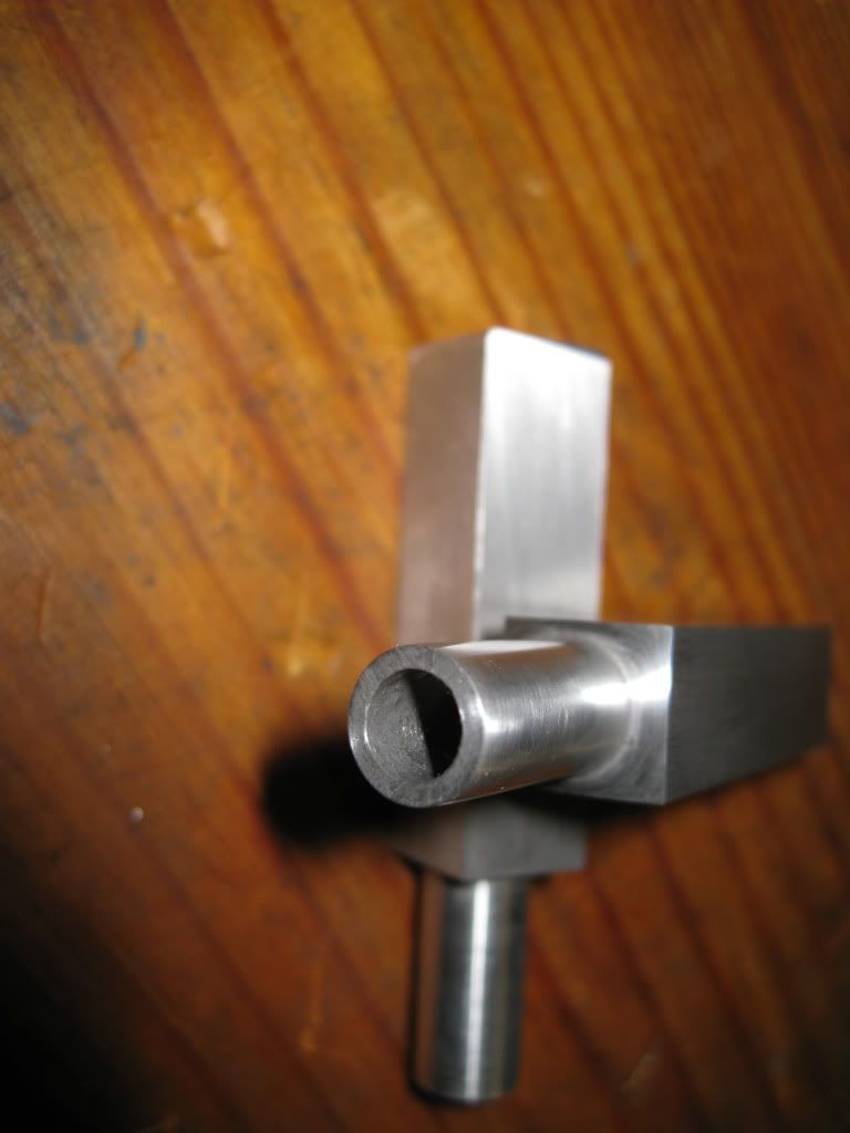
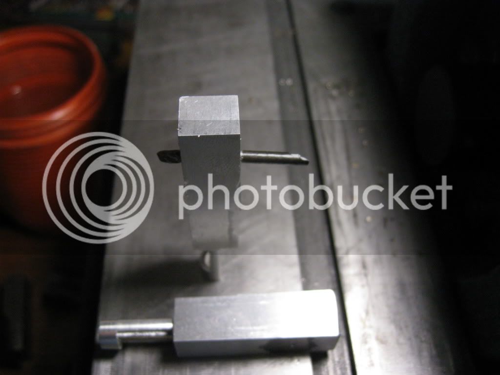
The cylinder rod guide is set up to be machined. Previous to this photo, I machined the bottom side of the guide.
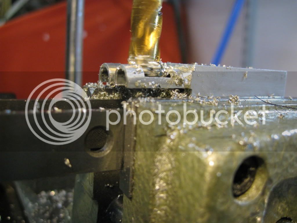
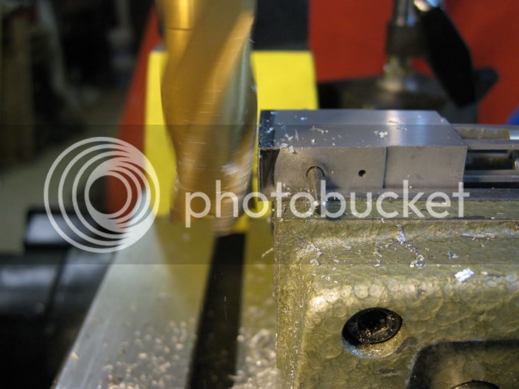
TwinWobbler032610071.jpg


I’m starting to get some time invested in the cylinders. I drilled the 1/8” holes for the cylinder pivots.
TwinWobbler032610074.jpg


What you see is a broken drill sticking out of the left side. On the right side you see a broken punch. I got my bigger hammer out and removed the offending materials. The part was saved. It must have been divine intervention, because I was ready to recycle it.
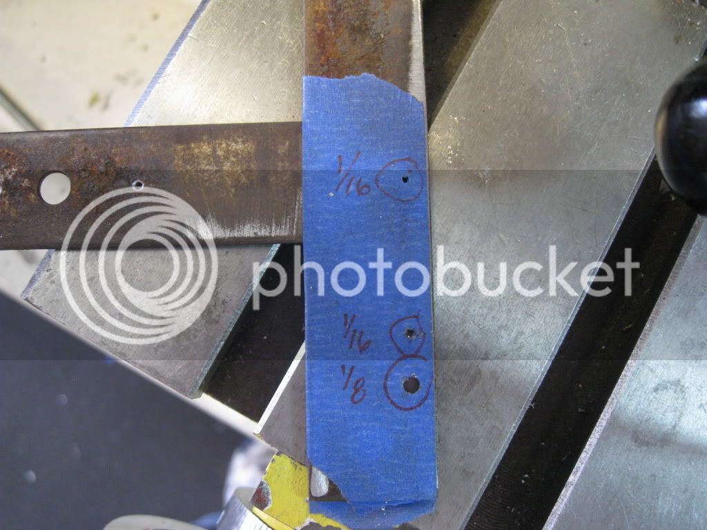
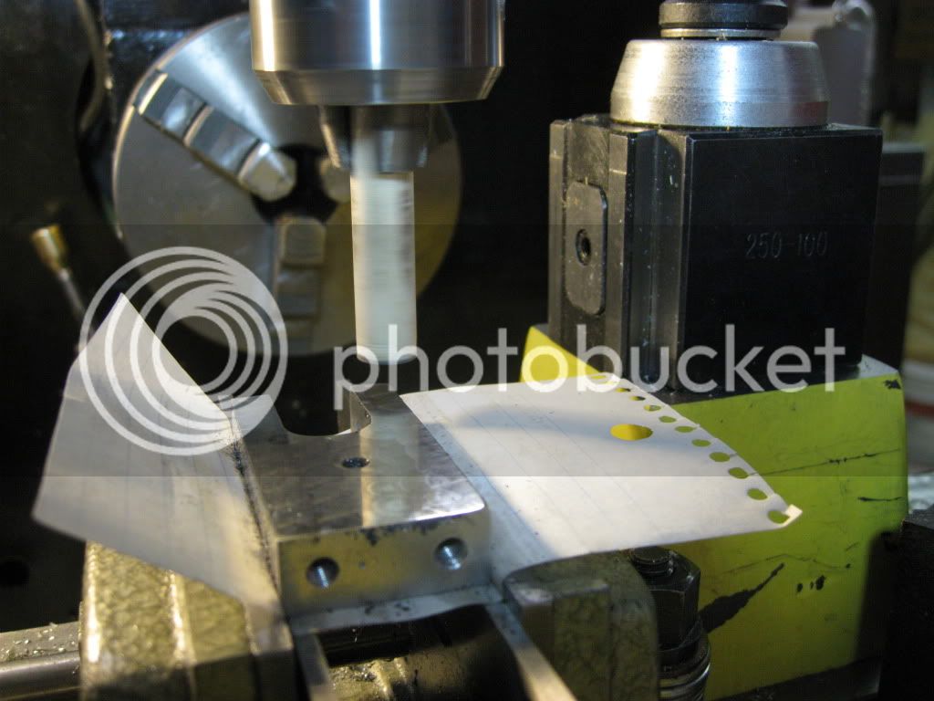
Time to drill the intake and exhaust ports on each side of the column. I made up a metal template from an old tee strap I had in my hardware box. I covered both sides of the template to protect the Aluminum from being scratched.
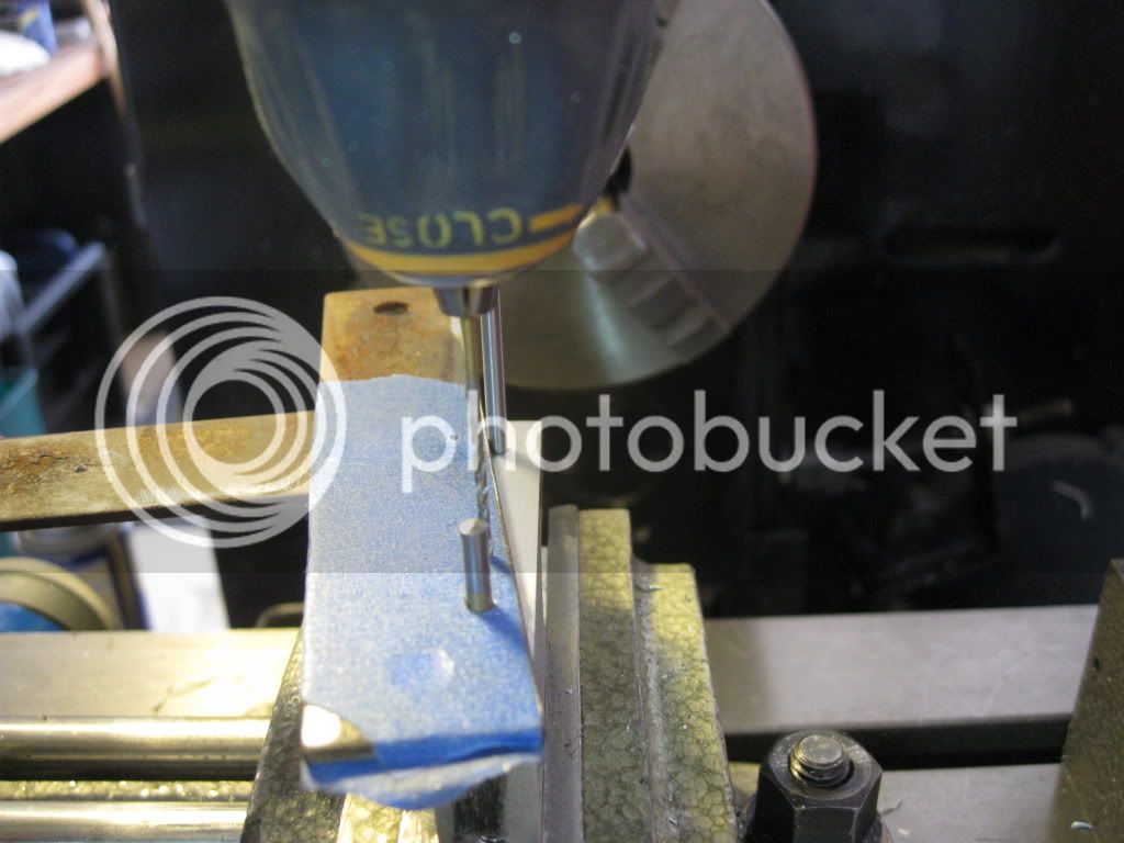
TwinWobbler032610006.jpg


Using the template

TwinWobbler032610003.jpg


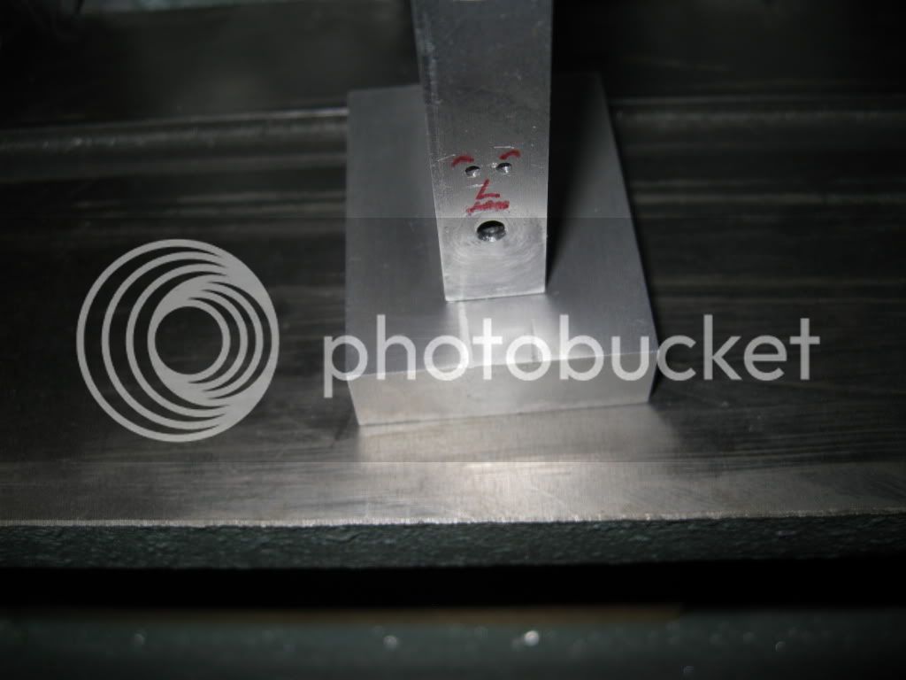
When I took this picture of the column, the camera recognized the 3 lower holes as being a face. Must be pretty sophisticated software to do that.

TwinWobbler032610014.jpg


Drilled for the flywheels set screw.
TwinWobbler032610008.jpg


I made up the 1/8” pivot shaft and crank shaft from some mild steel rod I found at Home Depot. The plans called for 5-40 threads on the ends of the pivot shaft. I didn’t have a die that size and H.D. didn’t have 5-40 nuts. I threaded the pivot rod 6-32 and used jam nuts since the thread was undersized. Smaller tap and dies are on my shopping list. I need to order some various sizes of ground drill rod for shaft material. I’m afraid that not using ground rod for the shafts will cost me running at slow speeds. Several 1/16” drill bits were broken during this build. I was able to use the ends for the crank pins. The pieces were loctited into the crank discs.
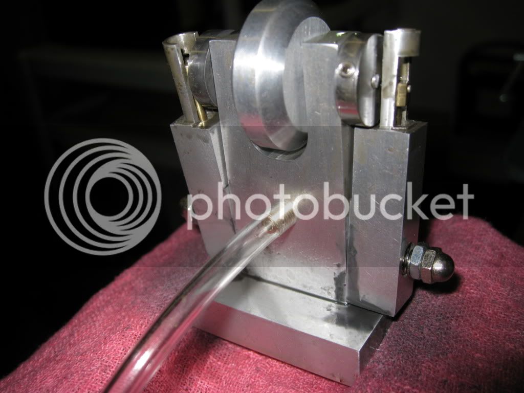
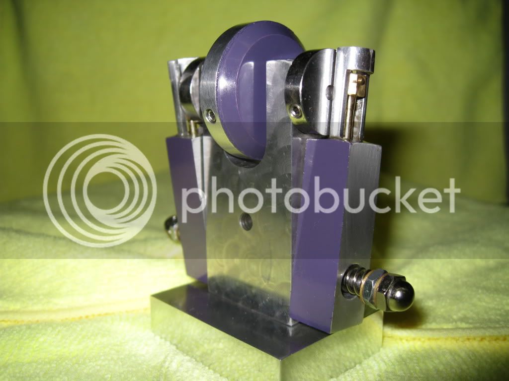
The engine was assembled and run in before I spent much time on surface finishes.
[ame]http://www.youtube.com/watch?v=xmdBywJy7fE[/ame]


TwinWobbler0326100142.jpg


Time to tear it down and start reducing the clear steam consuming friction.

TwinWobbler032610025.jpg


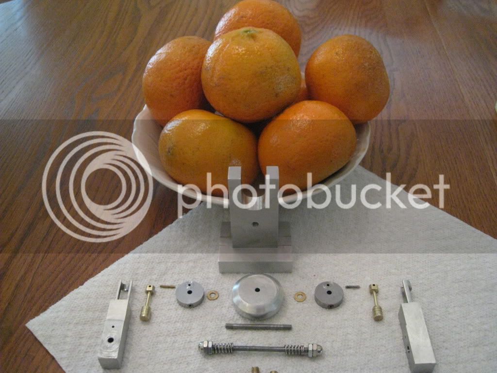
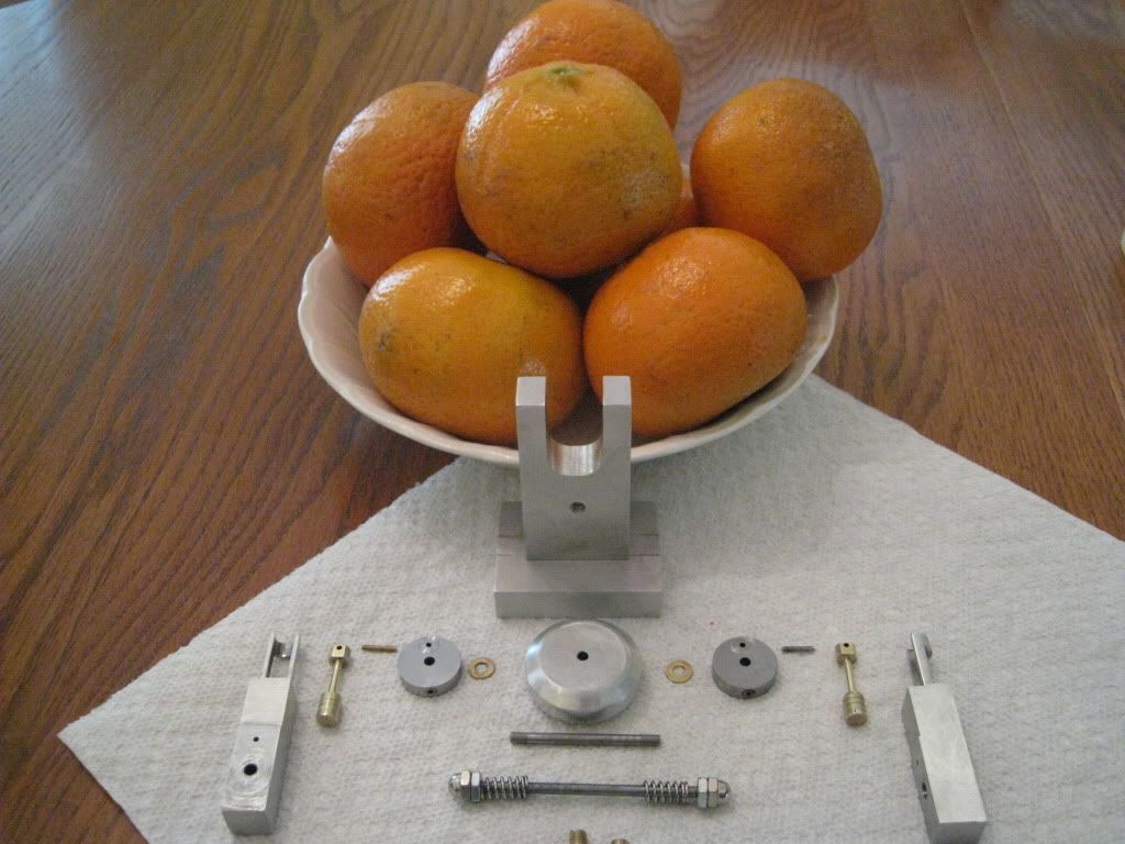
This artistic shot has been described by the Web renowned Art Critic, GWRdriver, in the following statement;

Quote from: GWRdriver on March 30, 2010, 02:27:27 PM
What a clueless lot you are . . . of COURSE this is art. It's one of a well-known series of photo-seriagraphs of fruit and metal which juxtaposes the linear industrial hardness, rigidity, and coldness of machined metal against the natural, organic, and random textures and arrangement of the paper towel, wood grain, and fruit which creates an allegory of the struggle of nature against industry. Seriagraph #12 in the series, the "Gearwheel and Grapes" image, is a masterpiece.

I used a piece of 1/8” rod to align the cylinders before machining the unnecessary material from the bottom end.

TwinWobbler032610002.jpg


TwinWobbler032610004.jpg


I’m attempting various finishing techniques as I go along. I gave engine turning a shot.
TwinWobbler032610007.jpg


In retrospect, I think I should have been more aggressive with the pressure and duration. Live and learn.
A little paint and polish never hurts.
TwinWobbler032610015.jpg


When I get some 1/8” drill rod and 5-40 dies and nuts, I’ll replace the pivot and crank shafts. I’ll also trim the springs or find some lighter force ones in an effort to reduce the minimum speed I can achieve.
Many thanks to the Machinist’s that make up this forum. I learn something from every build I read.
SAM
04/02/2010
[ame]http://www.youtube.com/watch?v=4R5QREOqYp0[/ame]

4/3/10 I corrected some typos and added a link to the break in video.
 
Thanks for the blow by blow, Sam. You seem to have a pretty good handle on how to get things done.
The pics are great.

Dean
 
Sam,

Very nice engine and super write-up.

By trying to save time, I ended up having to do it twice.

Man, I can relate to that!

Dennis
 
Sam very good details,
and as usual very fast smooth runners.

I'd venture to say you got a good working knowledge of how these wobblers work, where you could design your own from scratch..
And have it working just as fast and smooth as your other engines.

Keep up the good work...
 
Sam,

Very nice write up indeed, and a good result with the engine, even showing the non too successful bits (engine turning). It is those bits that transfer the most knowledge.

Don't worry too much about bling at the moment, that will come as a natural progression of your machining, the better your machining gets, the easier bling becomes. Shiny appears as if by magic.


Bogs


Latest posts

Back
Top